SLVUBX5B August 2023 – February 2024 TPS25762-Q1 , TPS25772-Q1
A TPS257xx-Q1 GUI Feature - CUSTOM ID (Version Control)
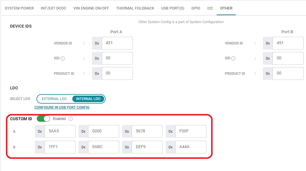
There are two ways to version control a GUI-generated binary file. The first method is automatically implemented when a binary is generated, as covered in Section 5, and a timestamp will be included within the file name. In some cases, however, it is desirable to be able to uniquely identify a binary file that is loaded into an EEPROM using an EEPROM reader such as an Aardvark adapter (see Section 5.4). This can be done by integrating a user-defined version control to the binary file using the CUSTOM ID feature on the OTHER tab from the Advanced Configuration GUI page (see Figure 7-1).
 Figure A-1 CUSTOM ID Menu
The CUSTOM ID feature is disabled by default. By enabling it, custom-defined values can be added to four input boxes per port. A 16-bit value can be entered in each box represented in hexidecimal format, so values up to 8 bytes for TPS25762-Q1 ("A" field only) and 16 bytes for TPS25772-Q1 ("A+B" fields) are possible.
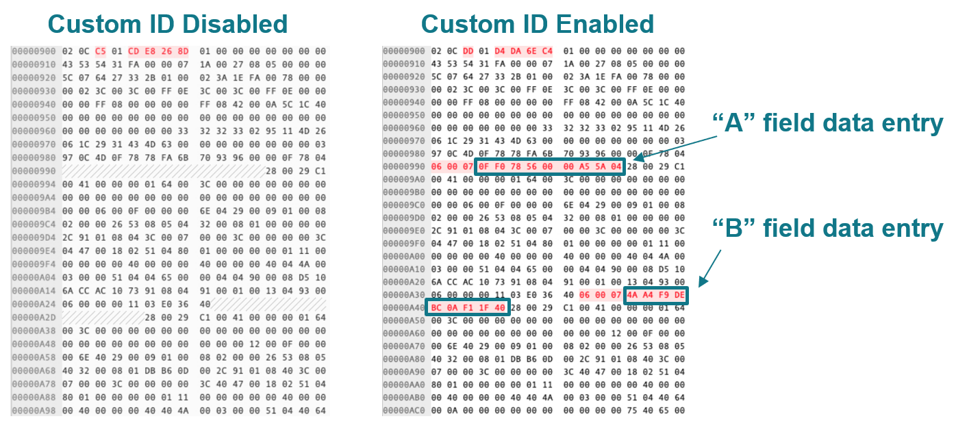
Figure 7-2 shows a comparison of two binary output files with the CUSTOM ID feature disabled and enabled. The same "A" and "B" field data entries from Figure 7-1 are highlighted in the CUSTOM ID enabled binary shown below. Note that the custom-defined values in the binary are assembled least significant byte first.
 Figure A-2 Binary Files with CUSTOM ID
Enabled vs. Disabled
Figure A-2 Binary Files with CUSTOM ID
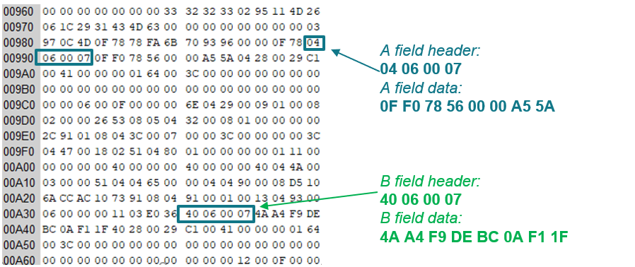
Enabled vs. DisabledThe byte position of the CUSTOM ID data may vary in the binary file depending on how the device features are configured. The "A" field data entry and "B" field data entry are preceded with their respective headers that are always the same (see Figure 7-3); the header for the "A" field is 04 06 00 07 and the header for the "B" field is 40 06 00 07. Searching for the header within the binary file will allow for easy identification of the CUSTOM ID data.
 Figure A-3 CUSTOM ID Data Headers
Although a binary file is time stamped in the file name when it is generated using the GUI, the CUSTOM ID feature is a more reliable way to embed a custom revision/version identifier. It is integrated into the binary file generation and it can be read out of the EEPROM directly for verification purposes.