SLYT816 October 2021 TPS548B27 , TPS548B28
4 Thermal comparison
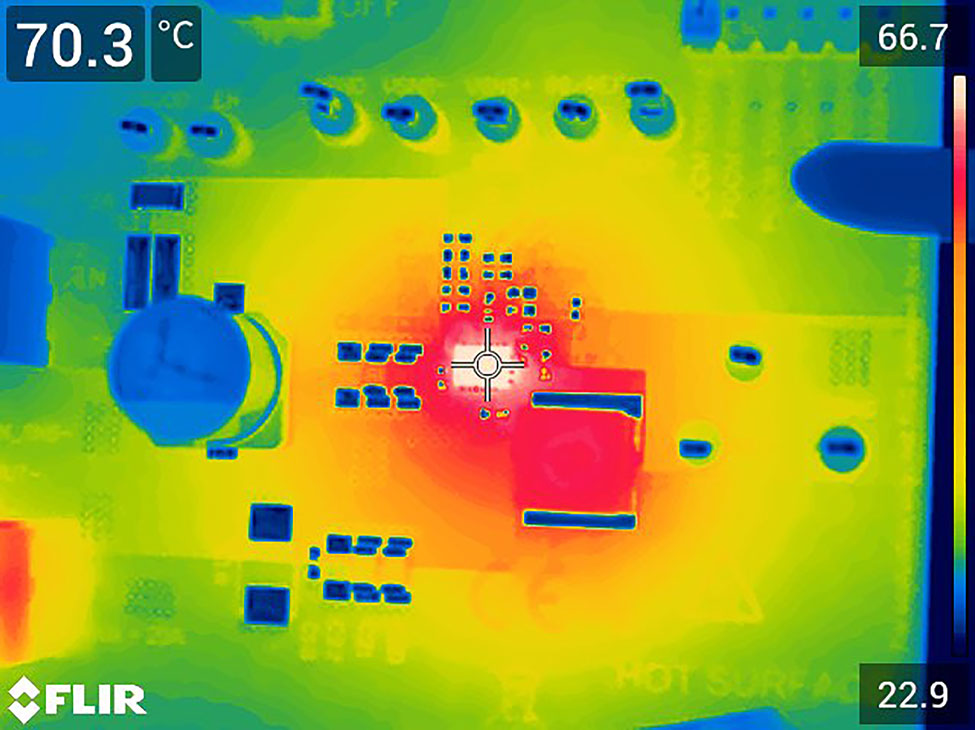
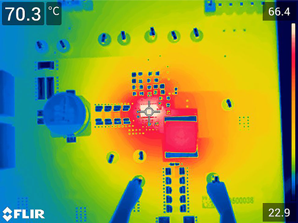
Each circuit board was operated at a 15-A current and measured the IC temperature of each design while operating under the same conditions. The IC temperature of the Enhanced HotRod QFN package was 70.3°C, shown in Figure 4-1. The HotRod package was also 70.3°C, shown in Figure 4-2. No other notable differences were observed. It is safe to conclude that any temperature variation between the two package examples would likely be caused by the IC’s lot-to-lot process variations, such as the drain-to-source on-resistance (RDS(on)) or the switching frequency. The Enhanced HotRod QFN package offered no improvement or degradation of thermal performance compared to the HotRod package.
 Figure 4-1 Enhanced HotRod QFN package
thermal image
 Figure 4-2 HotRod package thermal
image