SNAA390 july 2023 LMK6C , LMK6D , LMK6H , LMK6P
- 1
- Abstract
- Trademarks
- 1Introduction
- 2Test Standards and Test Setup
- 3Sinusoidal Vibration, Random Vibration, and Mechanical Shock Tests
- 4Comparison of BAW Oscillator Vibration Performance With Crystal Oscillator
- 5Summary
- 6References
3.2.2 Results From Random Vibration Test
The plots shown in this section are captured before, during, and after the random vibration test, which are tested following the MIL-STD-883F method 2026C.
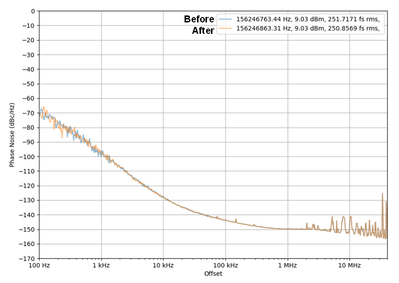
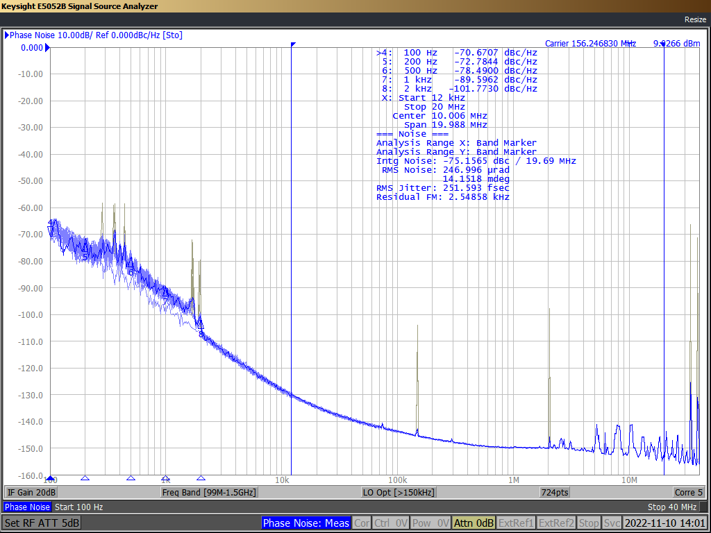
The capture data for the Z-axis movement of the DLE 4-pin (LVCMOS) oscillator is shown in Figure 3-15 and Figure 3-16.
 Figure 3-15 Plot of Before and After
Vibration Test on 4-pin DLE (LVCMOS)
 Figure 3-16 Capture During Vibration
of the 4-pin DLE (LVCMOS)
Figure 3-16 Capture During Vibration
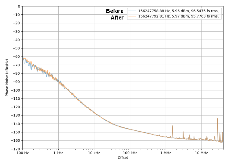
of the 4-pin DLE (LVCMOS)The capture data for the Z-axis movement of the DLE 6-pin (LVPECL) oscillator is shown in Figure 3-17 and Figure 3-18.
 Figure 3-17 Plot of Before and After
Vibration Test on 6-pin DLE (LVPECL)
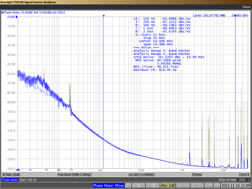
 Figure 3-18 Capture During Vibration
Test on 6-pin DLE (LVPECL)
Figure 3-18 Capture During Vibration
Test on 6-pin DLE (LVPECL)The preceding plots show that the performance of the BAW Oscillator is robust during and after the vibration and the jitter performance is not degraded.