SNAA390 july 2023 LMK6C , LMK6D , LMK6H , LMK6P
- 1
- Abstract
- Trademarks
- 1Introduction
- 2Test Standards and Test Setup
- 3Sinusoidal Vibration, Random Vibration, and Mechanical Shock Tests
- 4Comparison of BAW Oscillator Vibration Performance With Crystal Oscillator
- 5Summary
- 6References
3.3.1 Procedure for Mechanical Shock Test
For the mechanical shock test, the MIL-STD-883F Method 2002, Condition A profile (500 g acceleration) and Condition B profile (1500 g acceleration) is used.
For this sinusoidal vibration test, the following variants are selected.
- LVCMOS Output: DLE-4 (3.2 x 2.5 mm), DLF-4 (2.5 x 2.0 mm)
- Differential Output: DLE-6 (3.2 x 2.5 mm), DLF-6 (2.5 x 2.0 mm)
The following are the steps involved in setting up the Device Under Test (DUT) board on the vibration fixture and for conducting the mechanical shock test.
- Parts are soldered down on the LMK6x evaluation module (EVM) and bolted to the mating plate, which is connected to the mechanical shock testing machine.
- The Agilent E3631A bench-top power supply is setup to supply 3.3 V for the EVM module.
- For differential outputs (DLE-6 and DLF-6 package devices), the LVPECL output termination is provided on the EVM. A TC1-1-13MA+ Balun surface mount RF transformer is used to convert the differential output to a single-ended output and the output is connected to a Keysight E5052B phase noise analyzer.
- Shock parameters are set as
below
- For 1500 g, board is vertically lifted 10.4 inches.
- For 500 g, board is vertically lifted 3.8 inches.
- Air suction pulls fixture down to achieve appropriate g-force.
- At least 3 cycles of shock are performed for each tested sample.
- Transient data is acquired during shock test.
- Phase noise data is collected as a screenshot after shock test
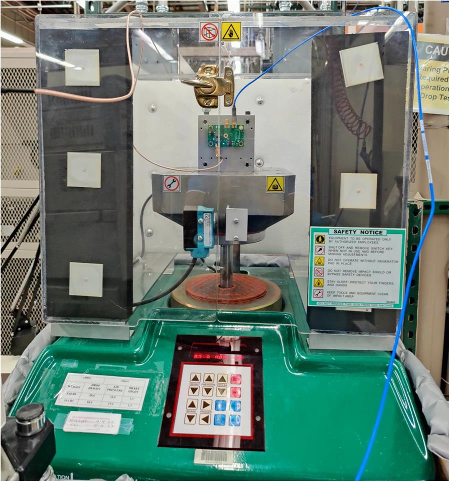
The shock test fixture setup is in Figure 3-19, which shows the mounted LMK6x EVM.
 Figure 3-19 Shock Test Setup