SNAU246A June   2020  – January 2021 LMX2820


  1. 1Trademarks
  2. 2LMX2820EVM Evaluation Module
    1. 2.1 Evaluation Module Contents
    2. 2.2 Evaluation Setup Requirement
    3. 2.3 Resources
  3. 3Setup
    1. 3.1 Connection Diagram
    2. 3.2 Power Supply
    3. 3.3 Reference Clock
    4. 3.4 RF Output
    5. 3.5 Programming
    6. 3.6 Evaluation Software
  4. 4Typical Measurement
    1. 4.1 Default Configuration
      1. 4.1.1 Loop Filter
      2. 4.1.2 Typical Output
    2. 4.2 Additional Tests
      1. 4.2.1 SYSREF Example
      2. 4.2.2 Offset Mixing With PFDIN Pin
      3. 4.2.3 External VCO Mode
      4. 4.2.4 Register Readback
  5. 5Schematic
  6. 6PCB Layout and Layer Stack-Up
    1. 6.1 PCB Layer Stack-Up
    2. 6.2 PCB Layout
  7. 7Bill of Materials
  8. 8Troubleshooting Guide
    1.     A Using Different Reference Clock
      1.      B USB2ANY Firmware Upgrade
        1.       C Revision History

External VCO Mode

In addition to the internal VCO, LMX2820 also support working with an external VCO. The polarity of the phase detector has to be set properly to match with the actual Vtune characteristic. The LMX2820EVM offers various options to implement passive or active loop filter onboard.
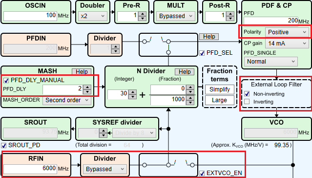
GUID-BBF737B2-42B1-4293-8561-396BEB273816-low.png Figure 4-5 External VCO Mode Setting