SPRACM9B June 2019 – November 2020 TMS320F28384D , TMS320F28384S , TMS320F28386D , TMS320F28386S , TMS320F28388D , TMS320F28388S , TMS320F28P650DH , TMS320F28P650DK , TMS320F28P650SH , TMS320F28P650SK , TMS320F28P659DH-Q1 , TMS320F28P659DK-Q1 , TMS320F28P659SH-Q1
- Trademarks
- 1 Introduction
- 2 Benefits of the TMS320F2838x MCU for High-Bandwidth Current Loop
- 3 Current Loops in Servo Drives
- 4 Outline of the Fast Current Loop Library
- 5 Fast Current Loop Evaluation
- 6 Incremental Build Level 1
- 7 Incremental Build Level 2
- 8 Incremental Build Level 3
- 9 Incremental Build Level 4
- 10Incremental Build Level 5
- 11Incremental Build Level 6
- 12Incremental Build Level 7
- 13Incremental Build Level 8
- 14References
- 15Revision History
5.1.4 SDFM
High-resolution, accurate, isolated phase current measurement is vital in automotive traction and servo drive applications, where high-performance torque and motion control are required. The options available for phase-current measurement are to use Hall-effect sensors, flux-gate sensors, current transformers, and shunt resistors. The first three options have inherent galvanic isolation benefits and a high current measurement range, but the linearity, bandwidth, and drift are of lower performance when compared to the shunt-resistor option. Shunt resistors provide a highly linear, high-bandwidth, and cost-effective measurement solution. Reinforced isolation provides both benefits of isolation and high linearity and bandwidth. Isolated shunt-based current measurement is accomplished either by using an isolated amplifier or an isolated delta-sigma modulator.
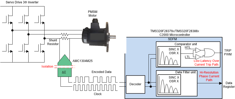
Figure 5-1 shows the mechanism of phase current sensing in servo drive motors, there are two paths implemented in the design, the high-speed bit stream output from the isolated modulators is filtered by TI's C2000 family real-time controllers that have a built-in sigma-delta filter module (SDFM), allowing the user to fine-tune signal bandwidth and accuracy. The SDFM is a four-channel digital filter designed specifically for current measurement in motor control applications. Each channel can receive an independent delta-sigma modulator bit stream which is processed by four individually programmable digital decimation filters. The filters include a fast comparator for immediate digital threshold comparisons for over-current and undercurrent monitoring. Also, a filter-bypass mode is available to enable data logging, analysis, and customized filtering. The SDFM pins are configured using the GPIO multiplexer. A key benefit of the SDFM is it enables a simple, cost-effective, and safe high-voltage isolation boundary.
 Figure 5-1 Current Sense Using
Delta-Sigma Modulator in Servo Drive
Figure 5-1 Current Sense Using
Delta-Sigma Modulator in Servo DriveOn the IDDK board, the voltage across the shunt resistor is fed into the AMC1304M25 sigma-delta modulator, which generates the sigma-delta stream that is decoded by the SDFM demodulator present on the C2000 MCU. The clock for the modulator is generated from the EPWM5 module on the C2000 MCU, and the AMC1304M25 data is decided using the built-in SDFM modulator.
To select the shunt-resistor based current sense with SDFM by setting the configuration in fcl_f2838x_tmdxiddk_settings_cpu1.h as shown below.
#define CURRENT_SENSE SD_CURRENT_SENSE