SPRUJ40C may 2022 – may 2023
- 1
- Abstract
- Trademarks
- 1EVM Revisions and Assembly Variants
-
2System Description
- 2.1 Key Features
- 2.2 Functional Block Diagram (SK-AM62 and SK-AM62B)
- 2.3 Functional Block Diagram (SK-AM62-P1 and SK-AM62B-P1)
- 2.4 AM62x SKEVM Interface Mapping
- 2.5 Power ON/OFF Procedures
- 2.6
Peripheral and Major Component
Description
- 2.6.1 Clocking
- 2.6.2 Reset
- 2.6.3 OLDI Display Interface
- 2.6.4 CSI Interface
- 2.6.5 Audio Codec Interface
- 2.6.6 HDMI Display Interface
- 2.6.7 JTAG Interface
- 2.6.8 Test Automation Header
- 2.6.9 UART Interface
- 2.6.10 USB Interface
- 2.6.11 Memory Interfaces
- 2.6.12 Ethernet Interface
- 2.6.13 GPIO Port Expander
- 2.6.14 GPIO Mapping
- 2.6.15 Power
- 2.6.16 AM62x SKEVM User Setup/Configuration
- 2.6.17 Expansion Headers
- 2.6.18 Interrupt
- 2.6.19 I2C Address Mapping
-
3Known Issues and Modifications
- 3.1 Issue 1 - HDMI/DSS Incorrect Colors on E1
- 3.2 Issue 2 - J9 and J10 Header Alignment on E1
- 3.3 Issue 3 - USB Boot descoped on E1
- 3.4 Issue 4 - OLDI Connector Orientation and Pinout
- 3.5 Issue 5 - Bluetooth descoped on E2 EVMs
- 3.6 Issue 6 - Ethernet PHY CLK Skew Default Strapping Changes
- 3.7 Issue 7 - TEST_POWERDOWN changes
- 3.8 Issue 8 - MMC1_SDCD spurious interrupts
- 3.9 Issue 9 - PD Controller I2C2 IRQ Not Pinned Out
- 3.10 Issue 10 - INA Current Monitor Adress Changes
- 3.11 Issue 11 - Test Automation I2C Buffer Changes
- Regulatory Compliance
- Revision History
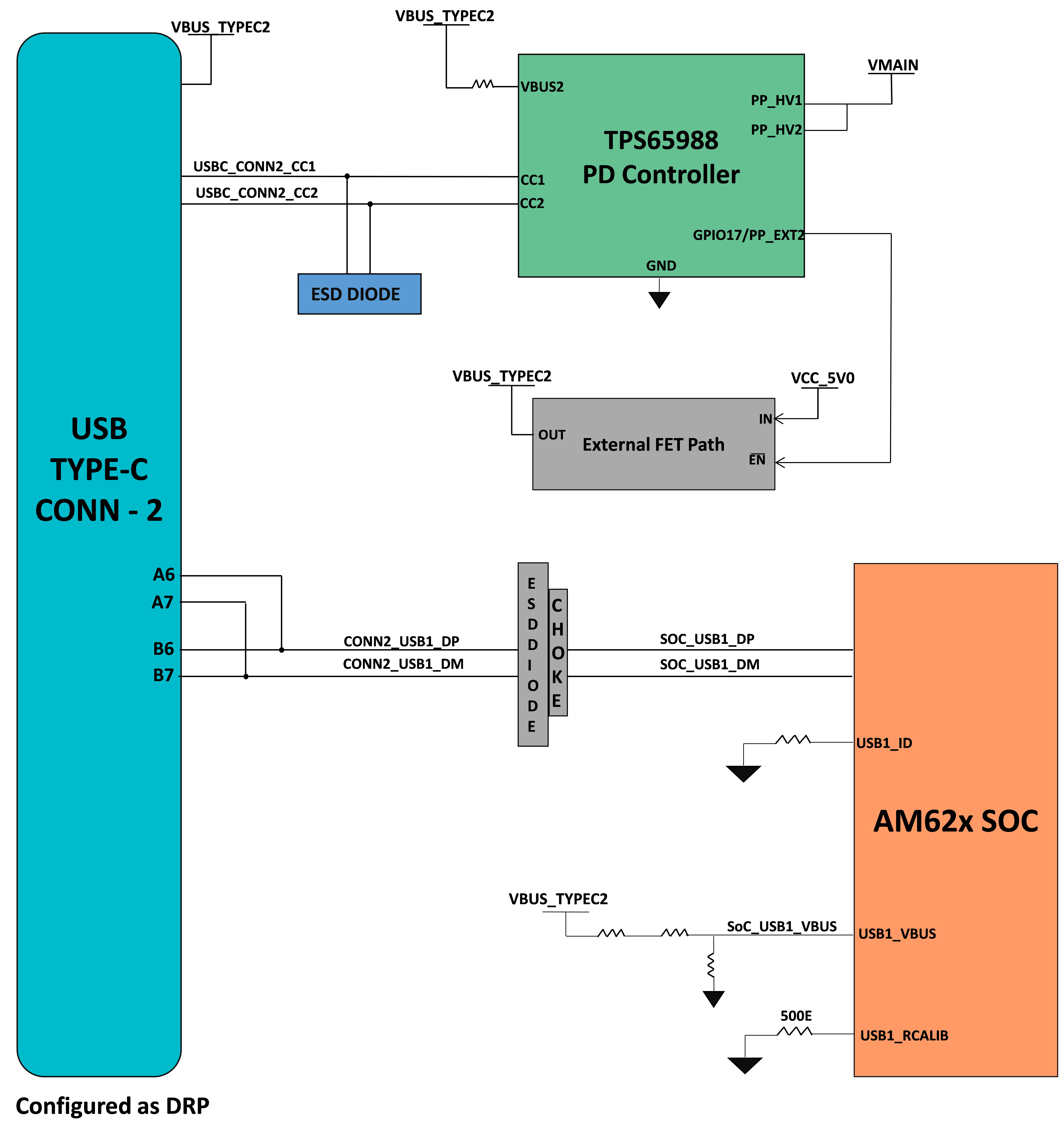
2.6.10.2 USB 2.0 Type C Interface
On SKEVM, USB 2.0 Interface is offered through USB Type-C Connector J13 Mfr part# 2012670005 that supports data rate up to 480 Mbps. J13 is used for Data communication and also as power connector. It is configured as DRP port using PD controller TPS65988DHRSHR IC, so it can act as either Host or Device. The role of the port depends on the type of the device getting connected on the connector and its ability to either sink or source. When the port is acting as DFP, it can source up to 5V@500mA.
USB 2.0 Data lines DP and DM from J13 are connected to the USB0 interface of AM62x SoC via choke and ESD protection device. USB0_VBUS to the SoC is provided through a resistor divider network.
A common mode choke of Mfr Part# DLW21SZ900HQ2B is provided on USB Data lines to take care of EMI/EMC. An ESD protection device of part number ESD122DMXR is included to dissipate ESD strikes on USB2.0 DP/DM Signals. An ESD protection device of part number TPD1E01B04DPLT is included on CC signals and TVS2200DRVR IC is included on VBUS rail of Type-C Connector J13 to dissipate ESD strikes.