SPRUJ40C may 2022 – may 2023
- 1
- Abstract
- Trademarks
- 1EVM Revisions and Assembly Variants
-
2System Description
- 2.1 Key Features
- 2.2 Functional Block Diagram (SK-AM62 and SK-AM62B)
- 2.3 Functional Block Diagram (SK-AM62-P1 and SK-AM62B-P1)
- 2.4 AM62x SKEVM Interface Mapping
- 2.5 Power ON/OFF Procedures
- 2.6
Peripheral and Major Component
Description
- 2.6.1 Clocking
- 2.6.2 Reset
- 2.6.3 OLDI Display Interface
- 2.6.4 CSI Interface
- 2.6.5 Audio Codec Interface
- 2.6.6 HDMI Display Interface
- 2.6.7 JTAG Interface
- 2.6.8 Test Automation Header
- 2.6.9 UART Interface
- 2.6.10 USB Interface
- 2.6.11 Memory Interfaces
- 2.6.12 Ethernet Interface
- 2.6.13 GPIO Port Expander
- 2.6.14 GPIO Mapping
- 2.6.15 Power
- 2.6.16 AM62x SKEVM User Setup/Configuration
- 2.6.17 Expansion Headers
- 2.6.18 Interrupt
- 2.6.19 I2C Address Mapping
-
3Known Issues and Modifications
- 3.1 Issue 1 - HDMI/DSS Incorrect Colors on E1
- 3.2 Issue 2 - J9 and J10 Header Alignment on E1
- 3.3 Issue 3 - USB Boot descoped on E1
- 3.4 Issue 4 - OLDI Connector Orientation and Pinout
- 3.5 Issue 5 - Bluetooth descoped on E2 EVMs
- 3.6 Issue 6 - Ethernet PHY CLK Skew Default Strapping Changes
- 3.7 Issue 7 - TEST_POWERDOWN changes
- 3.8 Issue 8 - MMC1_SDCD spurious interrupts
- 3.9 Issue 9 - PD Controller I2C2 IRQ Not Pinned Out
- 3.10 Issue 10 - INA Current Monitor Adress Changes
- 3.11 Issue 11 - Test Automation I2C Buffer Changes
- Regulatory Compliance
- Revision History
Regulatory Compliance
Hereby, Texas Instruments declares that the radio equipment, "AM62x Starter Kit for the Sitara Processors" is in compliance with directive 2014/53/EU.
The full text of the EU declaration of confirmity is available in the following website.
RF Exposure Information
This device has been tested and meets applicable limits for Radio Frequency (RF) exposure. This equipment should be installed and operated to ensure a minimum of 20 cm spacing to any person at all times.
EIRP Power
The maximum RF power transmitted in WLAN 2.4GHz band is 19 dBm. The maximum RF power transmitted in WLAN 5GHz band is 19.4 dBm (5150 MHz ~ 5350 MHz) and 18.4 dBm (5470 MHz ~ 5725 MHz).
The maximum RF power transmitted in Bluetooth is 14 dBm and Bluetooth Low Energy (BLE) is 8.9 dBm.
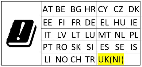
The device is restricted for indoor use only within the 5.15 - 5.25GHz band. The following are the countries with restricted indoor use,
Waste Electrical and Electronic Equipment (WEEE)

This symbol means that according to local laws and regulations your product and/or its battery shall be disposed of separately from household waste. When this product reaches its end of life, take it to a collection point designated by local authorities. Proper recycling of your product will protect human health and the environment.