SPRUJ40C may 2022 – may 2023
- 1
- Abstract
- Trademarks
- 1EVM Revisions and Assembly Variants
-
2System Description
- 2.1 Key Features
- 2.2 Functional Block Diagram (SK-AM62 and SK-AM62B)
- 2.3 Functional Block Diagram (SK-AM62-P1 and SK-AM62B-P1)
- 2.4 AM62x SKEVM Interface Mapping
- 2.5 Power ON/OFF Procedures
- 2.6
Peripheral and Major Component
Description
- 2.6.1 Clocking
- 2.6.2 Reset
- 2.6.3 OLDI Display Interface
- 2.6.4 CSI Interface
- 2.6.5 Audio Codec Interface
- 2.6.6 HDMI Display Interface
- 2.6.7 JTAG Interface
- 2.6.8 Test Automation Header
- 2.6.9 UART Interface
- 2.6.10 USB Interface
- 2.6.11 Memory Interfaces
- 2.6.12 Ethernet Interface
- 2.6.13 GPIO Port Expander
- 2.6.14 GPIO Mapping
- 2.6.15 Power
- 2.6.16 AM62x SKEVM User Setup/Configuration
- 2.6.17 Expansion Headers
- 2.6.18 Interrupt
- 2.6.19 I2C Address Mapping
-
3Known Issues and Modifications
- 3.1 Issue 1 - HDMI/DSS Incorrect Colors on E1
- 3.2 Issue 2 - J9 and J10 Header Alignment on E1
- 3.3 Issue 3 - USB Boot descoped on E1
- 3.4 Issue 4 - OLDI Connector Orientation and Pinout
- 3.5 Issue 5 - Bluetooth descoped on E2 EVMs
- 3.6 Issue 6 - Ethernet PHY CLK Skew Default Strapping Changes
- 3.7 Issue 7 - TEST_POWERDOWN changes
- 3.8 Issue 8 - MMC1_SDCD spurious interrupts
- 3.9 Issue 9 - PD Controller I2C2 IRQ Not Pinned Out
- 3.10 Issue 10 - INA Current Monitor Adress Changes
- 3.11 Issue 11 - Test Automation I2C Buffer Changes
- Regulatory Compliance
- Revision History
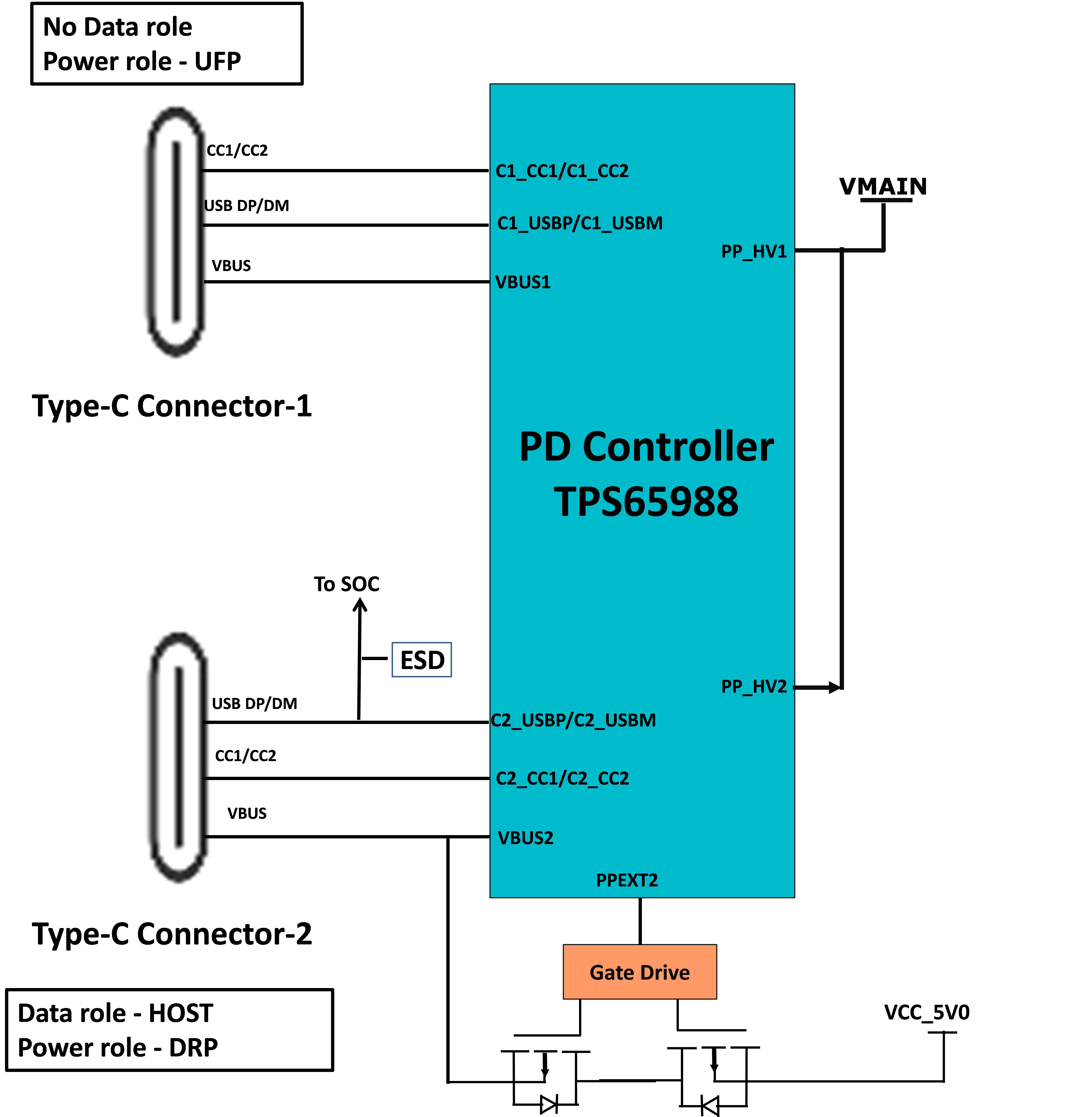
2.6.15.2 Power Input
Both Type-C Connectors (VBUS and CC lines) are connected to a Dual PD controller Mfr Part# TPS65988. The TPS65988 is a stand-alone USB Type-C and Power Delivery (PD) controller providing cable plug and orientation detection for two USB Type-C Connectors. Upon cable detection, the TPS65988 communicates on the CC wire using the USB PD protocol. When cable detection and USB PD negotiation are complete, the TPS65988 enables the appropriate power path. The two internal power paths of TPS65988 are configured as sink paths for the two Type-C ports and an external FET path is provided for Type-C CONN 2 to source 5 V when acting as DFP. The external FET path is controlled by GPIO17/PP_EXT2 of the PD controller.
TPS65988 PD controller can provide an output of 3A (15 V max) through CC negotiation. The VBUS pins from both the Type C connectors are connected to the VBUS pins of the PD controller. The output of the PD is VMAIN which is given to on board Buck-Boost and Buck regulators to generate fixed 5 V and 3.3 V supply for the SKEVM board.
The following sections describe the power distribution network topology that supplies the SKEVM board, supporting components and reference voltages.
The AM62x SKEVM board includes a power solution based on discrete power supply components. The initial stage of the power supply will be VBUS voltage from either of the two USB Type C connectors J11 and J13. USB Type-C Dual PD controller of Mfr. Part# TPS65988DHRSHR is used for negotiation of the required power to the system.
Buck-Boost controller LM34936RHFR and Buck converter LM61460-Q1 are used for the generation of 5V and 3.3V respectively and the input to the regulators is the PD output. These 3.3 V and 5 V are the primary voltages for the AM62x SKEVM Board power resources.
The 3.3 V supply generated from the Buck regulator LM61460-Q1 is the input supply to the Various SoC regulators and LDOs. The 5 V supply generated from the Buck Boost regulator LM34936RHFR is used for powering the onboard peripherals
Voltage divider network is used to provide the DDR_VREFCA (0.6 V) supply for the DDR4.
Discrete regulators and LDOs used on Board are:
- TPS62824DMQR – To generate VDD_2V5 rail for PHY and DDR peripherals
- TLV75510PDQNR – To generate VDD_1V0 for Ethernet PHYs
- TLV75511PDQNR – To generate VDD_1V1 for USB HUB
- TLV75512PDQNR – To generate VDD_1V2 for HDMI Transmitter
- TPS74518PQWDRVRQ1 – To generate 1.8 V Analog supply for SoC
- TPS6282518DMQR – To generate 1.8V IO supply for SoC
- TLV7103318QDSERQ1 – To generate VDDSHV5_MMC1(SD interface) supply for SoC
- TPS62824DMQR – To generate DDR supply for SoC and DDR
- TPS62826DMQR – To generate Core supply for SoC
- TPS74501PDRVR – To generate VDDR_CORE supply for SoC
Dedicated regulators are also provided on the board for:
- TPS62177 Regulator - Powering the always on circuits of Test Automation Section
- TLV75518 LDO -e-Fuse programming of SoC
- TPS79601 LDO - XDS110 On board emulator
- TPS73533 LDO - FT4232 UART to USB Bridge
Additionally, GPIO from the test automation header is also connected to the LM34936RHFR Enable to control ON/OFF of the SKEVM via the test automation board. It only disables the VCC_5V0 output of LM34936RHFR from which all other power supplies are derived. SoC has different IO groups. Each IO group is powered by specific power supplies as given in the table below.