SSZT752 april 2018 LM61460-Q1 , LMS3655-Q1 , TPS2561-Q1
Universal Serial Bus (USB) is an industry standard that defines cable, connector and communication protocols for facilitating the connection, communication and power-supply exchange between computers and devices. The use of USB in cars initially arose because consumers wanted an easy way to charge consumer electronics, but more recent applications of USB handle data transmission around the car. There are three types of connectors for USB ports: A, B and C. The type of port connector depends on whether the system port is downstream or whether the USB cable is carrying data. Type A is used solely for hub to hub (Figure 1).
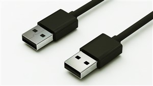 Figure 1 USB Type a Connector
TI has developed a 21W dual automotive USB charger solution (Figure 2), which is typical for modern automobiles today. It contains all of the necessary front-end protection against issues like double-battery, reverse-battery and load-dump conditions (compliant with International Organization for Standardization [ISO] 7630 Pulse 1, 2a, 3a/b) and support for deep cold-crank conditions. The 21W dual automotive USB design supports 2 x 2.1A for each of the USB ports and can charge two tablets or smartphones.
The Comité International Spécial des Perturbations Radioélectriques (CISPR) 25 Class 5 Rated Automotive USB Charger Reference Design with Full Front End Protection supports strict automotive electromagnetic interference (EMI) standards like CISPR 25 Class 5, and has a differential EMI filter to support conductive EMI suppression. This is particularly important, as any noise at the system level generated by this design could affect other electronic automotive systems. For example, poor filtering could cause a buzzing noise on the audio system.
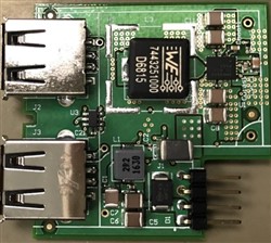 Figure 2 21w Dual Port USB Charging
Solution
Figure 2 21w Dual Port USB Charging
SolutionThe reference design connects directly to the automobile’s 12 V lead-acid battery and includes transient protection circuitry, an EMI filter and reverse-battery protection followed by the LMS3655-Q1 (for voltage regulation), theTPS2561-Q1 USB charging controller and the TPS2561-Q1 for dual-channel current limiting and power switching.
We designed the LMS3655-Q1 to support very low EMI switching noise by controlling the switch slew rate on the regulator, optimizing printed circuit board (PCB) layout and component placement, using jittering techniques like spread spectrum, reducing parasitic capacitors and inductance in the package. By controlling the fundamental EMI generation and limiting the switch node over ringing, it is possible to limit wideband noise generation. See Figure 3.
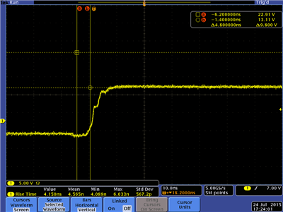 Figure 3 Switch-node LMS3655-Q1; Note
the Absence of Ringing
Figure 3 Switch-node LMS3655-Q1; Note
the Absence of RingingBy controlling the noise generation, it is possible to more easily handle EMI at the system level. By not generating the problem, you don’t need to then solve the problem later with PCB layout or by adding more components.
To verify the results, we tested our design in an EMI chamber under the documented conditions laid out within the CISPR 25 standard; see Figure 4. This design addresses one of the fundamental issues seen in other designs, which was noise leaking from the switch node to the edge connector. By limiting the EMI of the switch node in the design, there was no need for an additional metal shield for suppression. Having a design without such a component is not only more cost-effective but is also smaller and thinner, with the potential ability to run cooler.
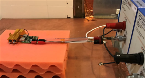 Figure 4 EMI Setup with PCB, without
Shielding
Figure 4 EMI Setup with PCB, without
ShieldingRunning a design cooler not only has power-saving benefits; it also limits the additional noise associated with high temperatures. Heat can limit the operating life of any system, and automotive systems have to survive many more years than your average consumer electronic device.
The LMS3655-Q1 operates at a sub-AM band to maximize efficiency, but TI also designed it at the integrated circuit (IC) level to operate at the highest level of integration, thermal performance and EMC through a combination of internal field-effect transistor (FET) selection, dead-time reduction and other techniques to minimize parasitic resistance. See Figure 5.
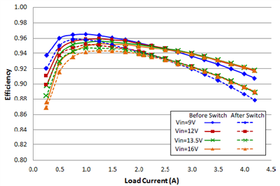 Figure 5 Efficiency Curves for the
LMS3655-Q1
Figure 5 Efficiency Curves for the
LMS3655-Q1USB designs are becoming smaller and integrating more features into a defined area. There’s less PCB copper for thermal dissipation for each of the individual component, and the plastic material used to contain the USB designs can add to self-heating. The LMS3655-Q1 offers high efficiency to minimize self-heating inside the design, also will operate at higher temperatures when there are challenging thermal limitations. Offering high levels of integration to minimize size, and features to minimize noise and solution cost. It can be used to overcome these challenges and assist the engineer to achieve a competitive solution. Get more information on TI’s products for automotive applications.
Read additional blogs on the topic of USB: