SWRA689 February   2022 AWR6843 , AWR6843AOP , IWR6843 , IWR6843AOP


  1.   Trademarks
  2. 1Introduction
  3. 2Radar System Overview
    1. 2.1 Architecture Overview
    2. 2.2 Equipment for Evaluation
      1. 2.2.1 Hardware
      2. 2.2.2 Software
    3. 2.3 Radar Measurement Cycle
  4. 3Active Mode Optimizations
    1. 3.1 Acquisition Period Overview
    2. 3.2 Acquisition Period Optimization Parameters
    3. 3.3 Acquisition Period Optimization Tradeoffs
    4. 3.4 Acquisition Period Optimization Implementation
      1. 3.4.1 Single Chirp Duration
      2. 3.4.2 Number of Chirps
      3. 3.4.3 Number of Tx Antennas
  5. 4Idle Mode Optimizations
    1. 4.1 Inter-Frame Period Overview
    2. 4.2 Idle Mode Techniques
      1. 4.2.1 Power Domain Components
        1. 4.2.1.1 DSP Power Domain Shutdown
      2. 4.2.2 Digital Domain Components
        1. 4.2.2.1 DSS Clock Gating (DSP Subsystem)
        2. 4.2.2.2 MSS VCLK to 40 MHz (Master Subsystem)
        3. 4.2.2.3 BSS Clock Gating (Radar Subsystem - BIST)
      3. 4.2.3 Analog Domain Components
        1. 4.2.3.1 RF Power Down (Radar Subsystem - Analog Front End)
        2. 4.2.3.2 APLL Power Down (Radar Subsystem - APLL)
      4. 4.2.4 Component Summary
    3. 4.3 Idle Mode Implementation
      1. 4.3.1 Idle Power CLI Configuration in 68xx Low-Power Demo
      2. 4.3.2 Example Invoking Idle Mode
        1. 4.3.2.1 Nominal Power Down Scheme
        2. 4.3.2.2 Full Power Down Scheme
        3. 4.3.2.3 Fast Power Down Scheme (Clock Gates Only)
  6. 5Power Measurement Methods and Results
    1. 5.1 Power Measurement Method
    2. 5.2 Idle Mode Power Measurements
      1. 5.2.1 Nominal Power Down Scheme Measurements
      2. 5.2.2 Full Power Down Scheme Measurements
      3. 5.2.3 Fast Power Down Scheme Measurements
  7. 6References

Architecture Overview

The highly integrated nature of the AWR/IWR6843 Sensor allows for varying schemes of power optimization. For example an application that makes use of only 1Tx/1Rx will see less power consumed during active chirp time than a multi-Tx/Rx application where more angular resolution is required. As such one should be aware of the various performance compromises that result from optimizing for power. However the benefit of integration allows the optimizations to be implemented through software that can even be configured at runtime.
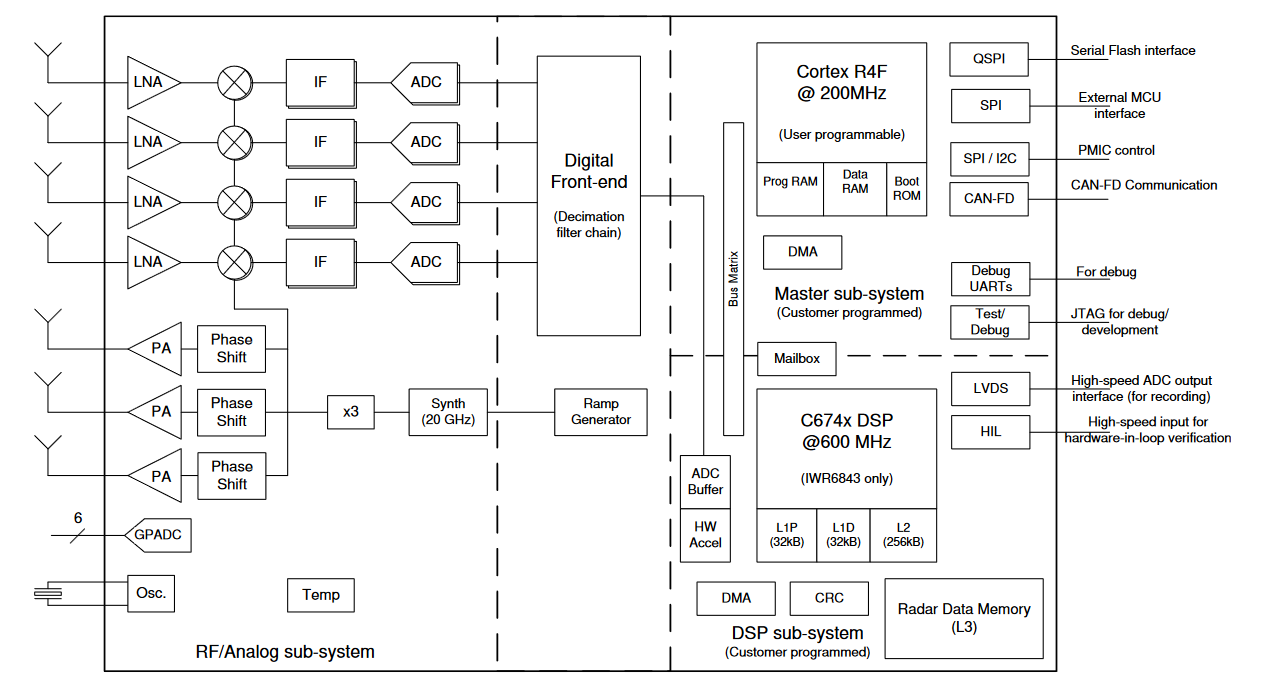
GUID-20220124-SS0I-QNNX-MPJ5-7ZPNKRM8QQTP-low.png Figure 2-1 AWR6843 Block Diagram