SWRA730 February 2022 CC1311P3 , CC1311R3 , CC1312R , CC1312R7 , CC1314R10 , CC1352P , CC1352P7 , CC1352R , CC1354P10 , CC1354R10
- Trademarks
- Acronyms
- 1Description of the PCB Antenna
- 2Test Setup
- 3Unmatched Results
- 4Single-Band Matching and Result
-
5Dual Band Matching and Results
- 5.1 433-MHz and 2440-MHz Smith Chart, SWR, Bandwidth, and Efficiency
- 5.2 470-MHz and 2440-MHz Smith Chart, SWR, Bandwidth and Efficiency
- 5.3 490 MHz and 2440 MHz Smith Chart, SWR, Bandwidth and Efficiency
- 5.4 510-MHz and 2440-MHz Smith Chart, SWR, Bandwidth, and Efficiency
- 5.5 868/915 and 2440-MHz Smith Chart, SWR, Bandwidth, and Efficiency
- 6Summary - Bill of Materials and Results
- 7Conclusion
- 8References
2.1 Radiation Pattern
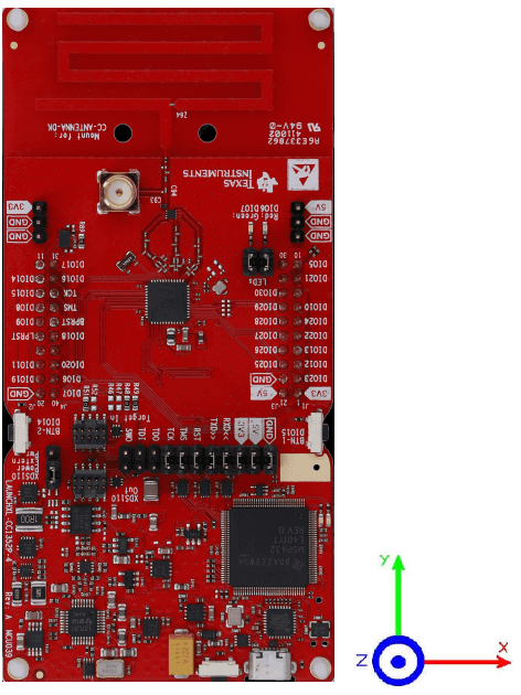
Figure 2-1 shows how to relate the radiation patterns in this application note to the orientation of the antenna.
Note that the size of the ground plane will affect the radiation pattern. Thus, implementing this antenna on a board with a different size and shape of the ground plane will most likely affect the radiation pattern.
 Figure 2-1 XYZ Coordinates for the
Antenna Radiation Plots