DLPA122 July 2021 DLP2010LC , DLP2010NIR , DLP3010LC , DLP4500 , DLP4710LC , DLP500YX , DLP5500 , DLP6500FLQ , DLP6500FYE , DLP670S , DLP7000 , DLPC200 , DLPC3470 , DLPC3478 , DLPC3479 , DLPC350 , DLPC410 , DLPC900
1 Application Brief
3D Machine Vision
3D machine vision is a fast and accurate optical technique used to capture physical details of an object. With the digitized 3D scan data, the dimensions of any object including; surface area, volume, and feature size can be extracted. Structured light is a method of 3D scanning where a series of patterns are projected upon an object and a camera or sensor detects distortions of the patterns. Image processing and triangulation algorithms then convert these distortions into a 3D point cloud. The point cloud can be used directly for analysis of the object or easily exported to a variety of CAD modeling formats.
TI DLP technology enables programmable structured light solutions for portable and high resolution applications. DLP systems can produce non-contact, highly accurate 3D data in real-time, facilitating 3D machine vision.
Features and Benefits
- Fast, programmable pattern rates up to 32
kHz
- Acquire 3D scan data in real-time on moving objects.
- Optimize scan speed and accuracy for multiple objects and environments using adaptive pattern sets.
- Precise depth capture
- Achieve measurement accuracy to sub μm level.
- Digital switching using reflective,
reliable MEMS micromirrors
- Consistent performance over time and temperature with minimal sensitivity to color and environment.
- Active illumination with LEDs, lasers, or
lamps
- Multiple wavelengths for scanning a wide range of materials.
- Enables strong low light performance.
DLP Solutions for 3D Machine Vision
DLP chipsets are available with different DMD (Digital Micromirror Device) sizes, pixel pitches, resolutions, and wavelength capabilities. The best choice for a DLP chipset can depend on the size of the scanning volume, pattern speed and system form factor. The table at the end of this document includes chipset offerings varying in resolution, speed and size. Higher resolution DMDs allow for a larger point cloud. High speed DMDs increase throughput with faster pattern speeds. Smaller DMDs allow for small form factor solutions.
Example Applications
- Factory automation
- Industrial robotics
- Medical imaging
- Dental scanning / intraoral scanning (IOS)
- Industrial metrology
- Biometrics
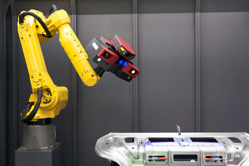
 Figure 1-1 3D Scanner Mounted on Robotic
Arm
Figure 1-1 3D Scanner Mounted on Robotic
ArmEvaluation Modules
Accelerate your design cycle by evaluating DLP technology with a broad selection of evaluation modules (EVMs). Our portfolio of EVMs offer a compelling combination of resolution, brightness, pattern speed, and programmability of DLP technology.
TI provides free software and firmware downloads allowing developers to easily create, store, and display high-speed pattern sequences through USB-based application programming interface (API) and easy-to-use graphical user interface (GUI).
To find an EVM, visit:
System Block Diagram
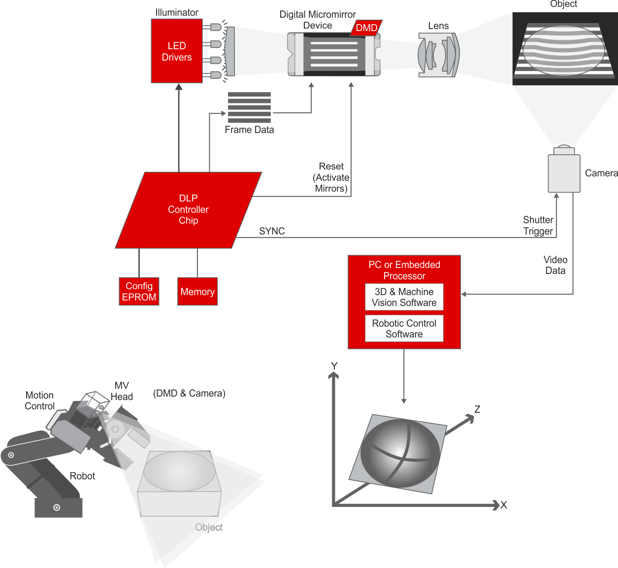
The DLP solution for 3D machine vision is shown in the diagram. DLP technology enables 3D machine vision capabilities by providing single or multiple camera 3D image capture. The system utilizes a DMD as a spatial light modulator and a DMD controller to provide high-speed control of the micromirrors. TI LED drivers provide illumination for the DMD to project the image. From power management to embedded processors to support the system, TI’s vast portfolio provides a complete system solution to create your ideal 3D machine vision design.
 Figure 1-2 System Block Diagram
Reference Designs and Ecosystem Support
There are several reference designs and third party modules to empower developers with a framework to build accurate 3D scanners and 3D machine vision systems. Reference designs include schematics, block diagrams, bills of materials, design files, software, and test reports. The reference designs and third party modules range from projection subsystems to full 3D scanner designs.
To learn more, visit Advanced Light Control Reference Designs, Explore Our Third-Party Solution Providers, and Optical Module Maker Search Tool.
| Digital Micromirror Device (DMD) | Micromirror Array Size | # of Pixels (MP) | # of Prestored Patterns | Max Pattern Rate (Prestored Patterns) (Hz) | Controller Part Number | Evaluation Module | ||||
|---|---|---|---|---|---|---|---|---|---|---|
| 1-bit | 8-bit | 16-bit | 1-bit | 8-bit | 16-bit | |||||
| DLP2010NIR | 854 × 480 | 0.41 | 64* | 8* | 2487 | 272 | DLPC3470 | |||
| DLP2010LC | 854 × 480 | 0.41 | 64* | 8* | 2487 | 272 | DLPC3470 | DLP2010EVM-LC | ||
| DLP3010LC | 1280 × 720 | 0.92 | 51-64* | 6-8* | 2487 | 272 | DLPC3478 | DLP3010EVM-LC | ||
| DLP4500 | 912 × 1140 | 1.04 | 48 | 6 | 4225 | 120 | DLPC350 | DLPLCR4500EVM | ||
| DLP4710LC | 1920 × 1080 | 2.07 | 60-64* | 7-8* | 2500 | 437 | DLPC3479× 2 | DLP4710EVM-LC | ||
| DLP5500 | 1024 × 768 | 0.79 | 960 | 120 | 5000 | 500 | DLPC200 | |||
| DLP6500 | 1920 × 1080 | 2.07 | 400 | 50 | 11574 | 1446 | DLPC900 | DLPLCR65EVM | ||
| DLP7000 | 1024 × 768 | 0.79 | N/A | 32552 | 4069 | 2034 | DLPC410 | DLPLCR70EVM | ||
| DLP500YX | 2048 × 1200 | 2.46 | 800 | 100 | 50 | 16100 | 2016 | 1008 | DLPC900× 2 | DLPLCR50XEVM |
| DLP670S | 2716 × 1600 | 4.35 | 400 | 50 | 9523 | 1190 | DLPC900× 2 | DLPLCR67EVM | ||
* Prestored patterns are column-repeat or row-repeat (1D) patterns