DLPU077A March 2019 – June 2019 DLPC4422
2.2 Connecting the DLPDLCR660TEVM, or DLPDLCR470TEVM, to the DLPLCRDC4422EVM
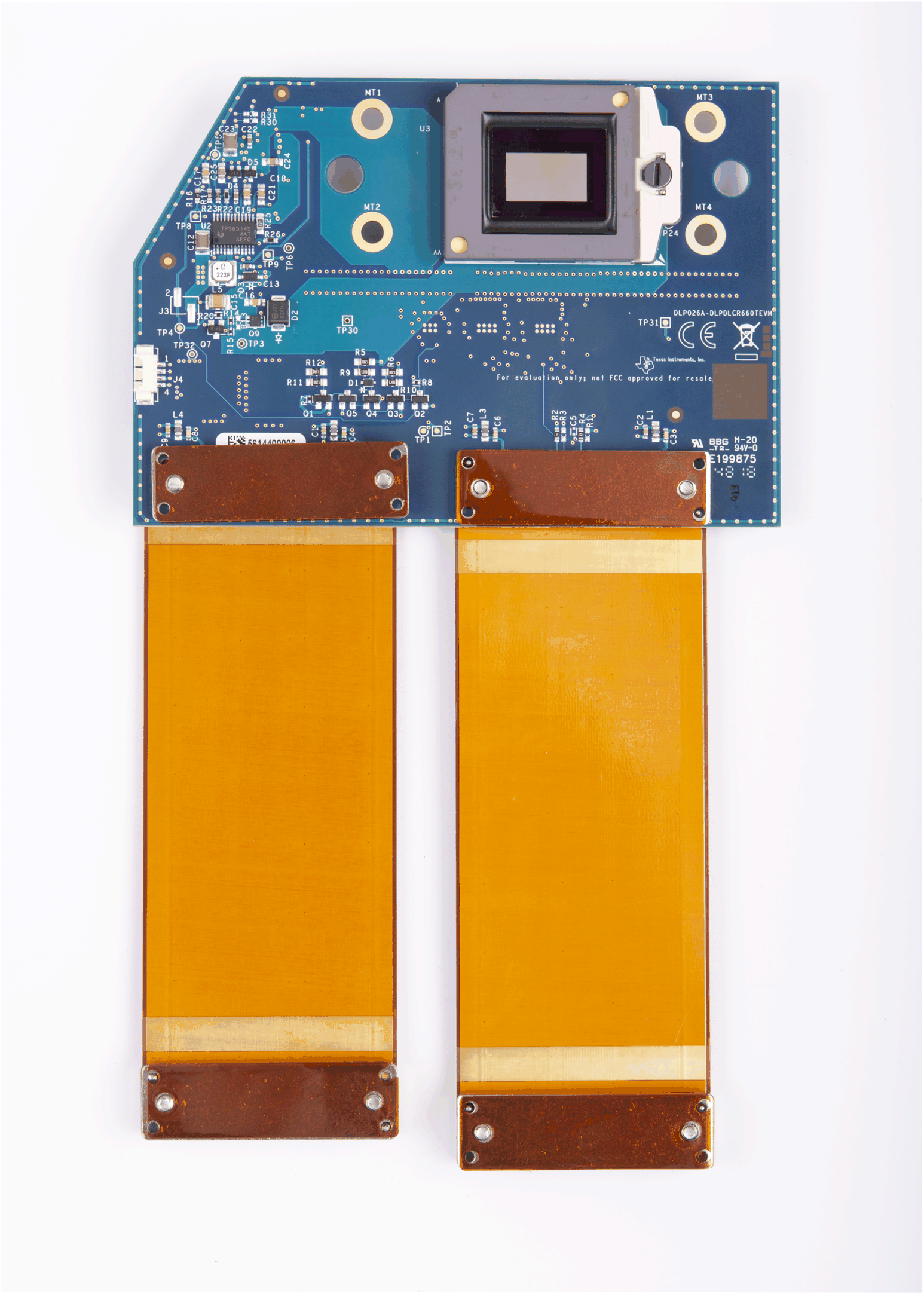
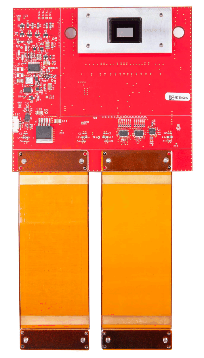
Before connecting the DLPDLCR660TEVM/DLPDLCR470TEVM to the DLPLCRDC4422EVM, locate the two flex cables that are packaged with either the DLPDLCR660TEVM/DLPDLCR470TEVM. Ensure the flex cables are not torn or damaged before connecting the DMD EVMs or the DLPLCRDC4422EVM.
The flex cables are exactly the same, meaning there is not a “right” or “left” cable. The cables are interchangeable, as long as the side of each cable labeled “DMD END” is connected to the DLPDLCR660TEVM/DLPDLCR470TEVM and the other end is connected to the DLPLCRDC4422EVM.
The steps for the connecting the EVMs are listed below:
- Unscrew and remove the backer plate on each end of the flex cable.
- Position the flex cable end which says “DMD END” to the backside of the DMD board.
- Insert the two guide pins of the flex cable into the DMD board.
- Using the guide pins, place one backer plate on the front side of the DMD board.
- Screw the flex cable screws clockwise into the backer plate until nearly fully inserted
- Take turns screwing in the screws so until each is lightly snug. Do not over-tighten.
 Figure 2-1 Flex Cables on DLPDLCR660TEVM
  Figure 2-2 Flex Cables on DLPDLCR470TEVM
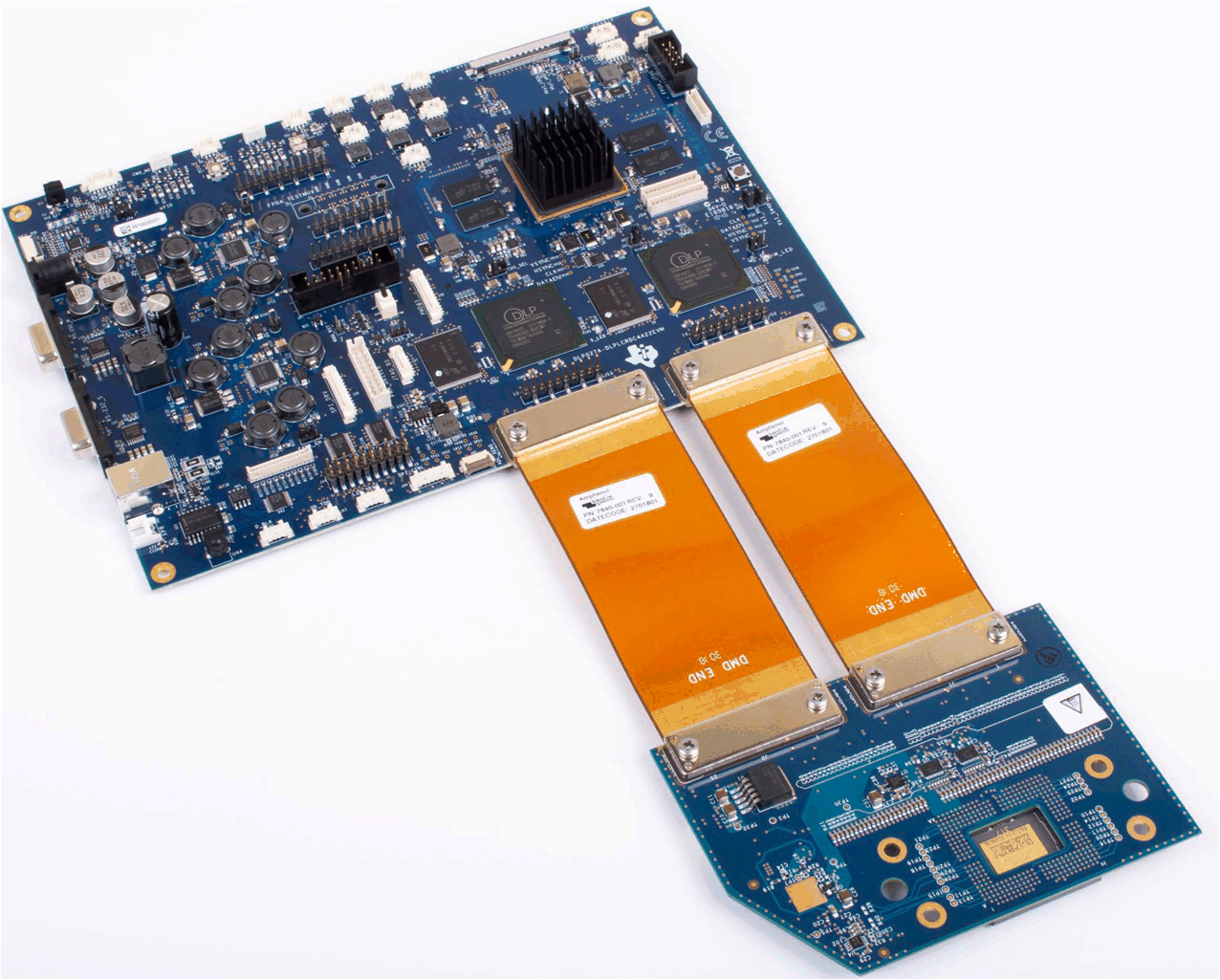
 Repeat the above steps to connect the other end of each flex cable to the DLPLCRDC4422EVM. The EVM should look like after the flex cables have been connected to both the DLPDLCR660TEVM and the DLPLCRDC4422EVM. The process is the same for use with the DLPDLCR470TEVM.
 Figure 2-3 EVMs Connected