DLPU082C August 2021 – March 2024 DLPC7540
- 1
- Abstract
- Trademarks
- 1 Scope
- 2 References
- 3 Acronyms
- 4 System Boot
- 5 System Status
- 6 Version
- 7 Power Modes
- 8 Display Modes
- 9 Source Detection and Configuration
- 10Internal Sources
- 11Display Formatting
- 12Image Processing
-
13Warping
- 13.1 Control Point Table
- 13.2 Manual Warp Table
- 13.3 Table Constraints
- 13.4 Example Warp Table
- 13.5
Manual Warping Commands
- 13.5.1 CMD_SetManualWarpControlPoints [Command ID: 0x35, Destination: 4]
- 13.5.2 CMD_GetManualWarpControlPoints [Command ID: 0x35, Destination: 4]
- 13.5.3 CMD_WriteManualWarpTable [Opcode: 0x34, Destination: 4]
- 13.5.4 CMD_ReadManualWarpTable [Opcode: 0x34, Destination: 4]
- 13.5.5 CMD_ConfigureSmoothWarp [Command ID: 0x38, Destination: 4]
- 13.5.6 CMD_ApplyManualWarping [Command ID: 0x36, Destination: 4]
- 13.6 Optical (Lens) Distortion Correction
-
14Introduction to Blending
- 14.1 Blend Map Control Points
- 14.2 Blend Map Gain Values
- 14.3 Blend Map Offset Value
- 14.4 Constraints
- 14.5
Manual Blending Commands
- 14.5.1 CMD_EnableEdgeBlending [Command ID: 0x2F]
- 14.5.2 CMD_SetBlendMapControlPoints [Opcode: 0x2E]
- 14.5.3 CMD_ GetBlendMapControlPoints [Command ID: 0x2E]
- 14.5.4 CMD_SetBlendMapGainValues [Command ID: 0x2B]
- 14.5.5 CMD_ GetBlendMapGainValues [Command ID: 0x2B]
- 14.5.6 CMD_ SetBlendMapOffsetValues [Command ID: 0x2D]
- 14.5.7 CMD_ GetBlendMapOffsetValues [Command ID: 0x2D]
- 14.5.8 CMD_ApplyBlendMap [Command ID: 0x2C]
- 14.6 Manual Blending Application Commands
- 14.7 Cropping of Input Image for Blending Setup
- 14.8 Storing Edge Blend Configuration in EEPROM
- 14.9 Storing in EEPROM or Secondary Flash
- 14.10 Manual Blending GUI in Control Program
- 15Illumination Control
- 16Peripherals
- 17Interface Protocol
- 18Command Protocol
- 19Auto-Initialization Batch File
- 20Command Descriptions
- 21System Commands
- Revision History
13.5.5 CMD_ConfigureSmoothWarp [Command ID: 0x38, Destination: 4]
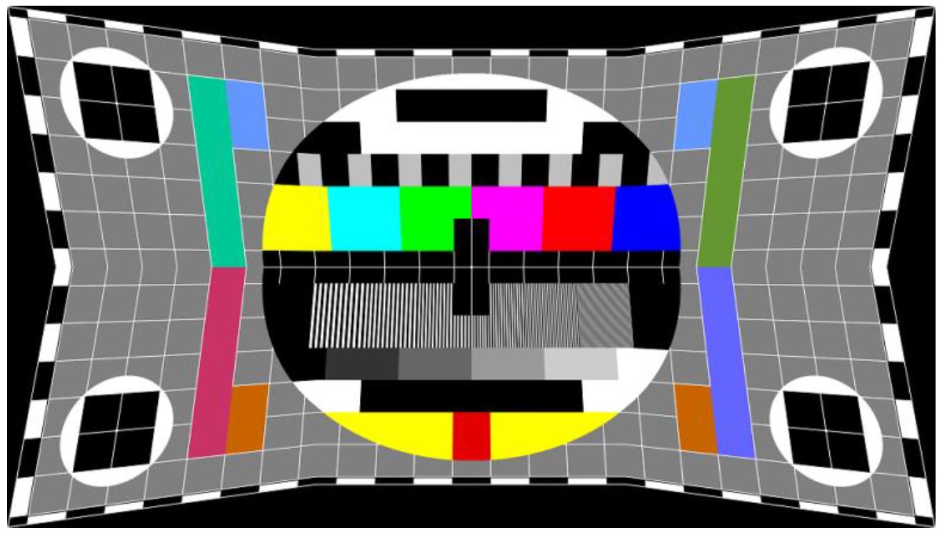
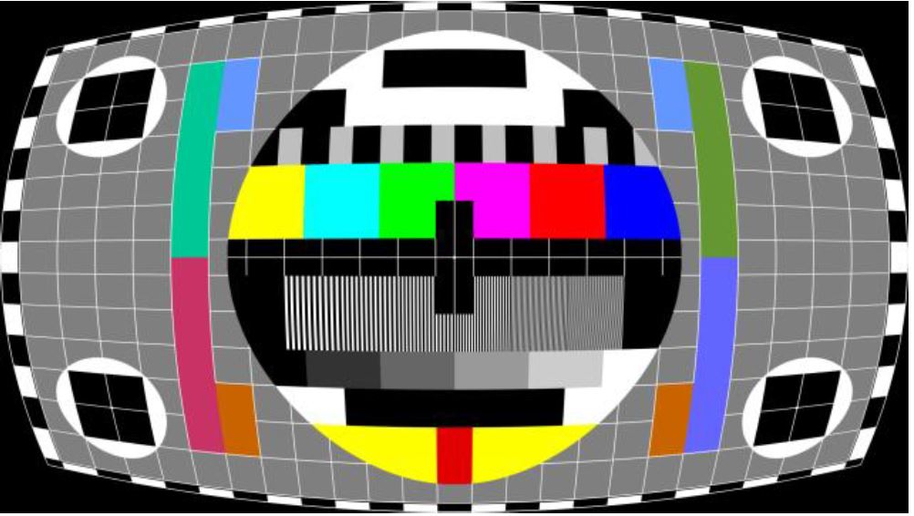
This command loads a manual warp table into the system. The edges connecting two warp points in this case are not straight lines but are ‘smoother’; that is, at the warp point, the edge is continuous and does not form a vertex (except for corners). This is done by fitting a 2nd degree polynomial curve (of the form of ax2 + bx + c) to warp points, contrary to the Write Manual Warp Table command which fits straight line to warp points.
Only a warp table with up to 5 rows and 5 columns (25 points) can be defined with this command.
Manual warp map is applied on top of any scaling and keystone correction.
Manual warp control points command is NOT required before using this command since it always assumes uniform 3x3 map.
 Figure 13-6 CMD_ConfigureSmoothWarp Example Output 1
 Figure 13-7 CMD_ConfigureSmoothWarp Example Output 2
| Byte Index | Value | Description |
|---|---|---|
| 0 | 0x44 | Command packet header (destination 4, response required) |
| 1 | 0x38 | Command opcode |
| 3-4 | 0x01 | X1 = 0.0 |
| 5-6 | 0x0000 | Y1 = 0.0 |
| 7-8 | 0x3C00 | X2 = 1920.0 |
| 9-10 | 0x0640 | Y2 = 200.0 |
| 11-12 | 0x77F8 | X3 = 3839.0 |
| 13-24 | 0x0000 | Y3 = 0.0 |
| 15-16 | 0x0640 | X4 = 200.0 |
| 17-18 | 0x21C0 | Y4 = 1080.0 |
| 19-20 | 0x3C00 | X5 = 1920.0 |
| 21-22 | 0x21C0 | Y5 = 1080.0 |
| 23-24 | 0x71C0 | X6 = 3640.0 |
| 25-26 | 0x21C0 | Y6 = 1080.0 |
| 27-28 | 0x0000 | X7 = 0.0 |
| 29-30 | 0x4378 | Y7 = 2159.0 |
| 31-32 | 0x3C00 | X8 = 1920.0 |
| 33-34 | 0x3D40 | Y8 = 1960.0 |
| 35-36 | 0x77F8 | X9 = 3839.0 |
| 37-38 | 0x4378 | Y9 = 2159.0 |