SBAU269C October 2016 – August 2021 ADS8900B
6.6 Linearity Analysis Tool
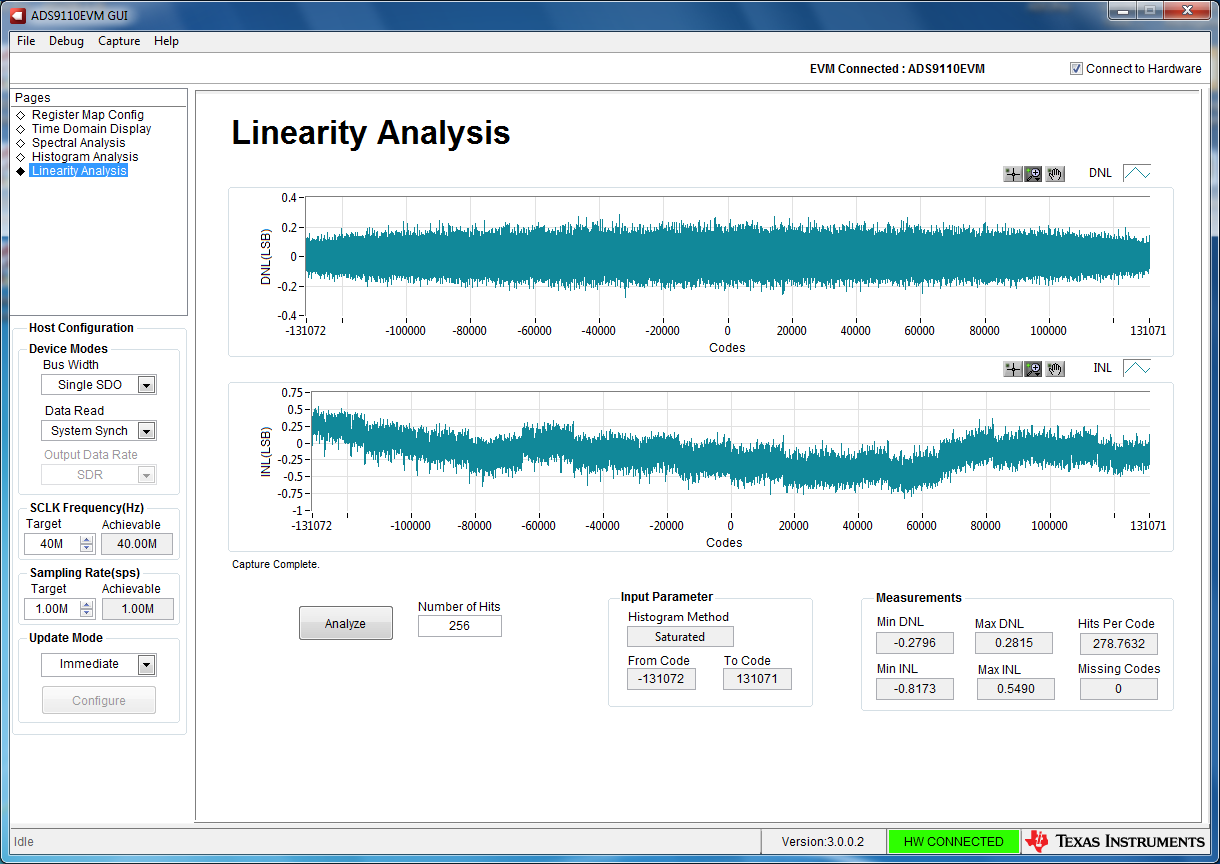
The linearity analysis tool (shown in Figure 6-9) measures and generates the DNL and INL plots over code for the specific ADS8900 installed in the evaluation board. This tool requires a 2-kHz sinusoidal input signal, which is slightly saturated (35 mV outside the full-scale range at each input or 0.13 dBFS) with very low distortion. The external source linearity must be better than the ADC linearity to ensure that the measured system performance reflects the linearity errors of the ADC and is not limited by the performance of the signal source. To make sure that the DNL and INL of the ADC are correctly measured, the external source must meet the requirements in Section 5.5.
This tool requires a negative supply on the THS4551 driver amplifier (U2). The easiest way to provide the negative supply is to install the negative charge pump LM7705 (U6). Also install the output filter capacitors and resistor associated with this charge pump (C31, C32, C33, C34, C35, C36, and R41).
The number-of-hits setting depends on the external noise source. For a 110-dB SNR external source with approximately 10 µVrms of noise, the total number of hits must be 512. For a source with 100-dB SNR, the recommended number of hits is 1024.
This analysis can take a couple of minutes to run and the evaluation board must remain undisturbed during the complete duration of the analysis.
 Figure 6-9 Linearity Analysis Tool