SBOU274A December   2021  – January 2022 OPT3004


  1.   Trademarks
  2. 1Overview
    1. 1.1 OPT3004DTSEVM Kit Contents
    2. 1.2 Related Documentation from Texas Instruments
  3. 2OPT3004DTSEVM Hardware
    1. 2.1 Theory of Operation for the OPT3004DTSEVM
    2. 2.2 OPT3004DTSEVM Hardware Overview
  4. 3OPT3004DTSEVM Software
    1. 3.1 Hardware Requirements
    2. 3.2 Software Installation
    3. 3.3 Typical OPT3004DTSEVM Hardware Setup
    4. 3.4 Launching the OPT3004EVM Software
    5. 3.5 OPT3004DTSEVM Software Operation
      1. 3.5.1 Getting Started
      2. 3.5.2 Feature Descriptions
        1. 3.5.2.1 Lux Plot
        2. 3.5.2.2 Drop-down Selectors
        3. 3.5.2.3 Save to File
        4. 3.5.2.4 Mean, Std, and the Blue Slider
        5. 3.5.2.5 Scripts Window
        6. 3.5.2.6 Overview of Device Registers
        7. 3.5.2.7 Additional Features of the Scripts Window
          1. 3.5.2.7.1 Hidden IDE Window
          2. 3.5.2.7.2 devInit.py
          3. 3.5.2.7.3 04-launchGUI.py
  5. 4Schematic, PCB Layout, and Bill of Materials
    1. 4.1 Coupon Board
      1. 4.1.1 Schematic
      2. 4.1.2 PCB Layout
      3. 4.1.3 Bill of Materials
    2. 4.2 Motherboard
      1. 4.2.1 Schematic
      2. 4.2.2 PCB Layout
      3. 4.2.3 Bill of Materials
  6. 5Troubleshooting
    1. 5.1 Microsoft Windows 7 Manual Driver Installation
  7. 6Revision History

Schematic

Figure 4-1 shows the complete schematic of the OPTMBEVM motherboard. The schematic is split into three sections: connector, MSP430, and socket. A USB type C connector is used to interface with the PC. The MSP430 microcontroller allows the PC to interface with the OPT3004DTS through I2C. The coupon board containing the OPT3004DTS plugs into the motherboard through the socket. The OPTMBEVM board provides easy access to the I2C, INT, VDD, and GND lines. The header J2 is depopulated on the EVM by default and its labeled through hole pads can be used to access the lines. Alternatively, a header can be populated at J2 for easier access.
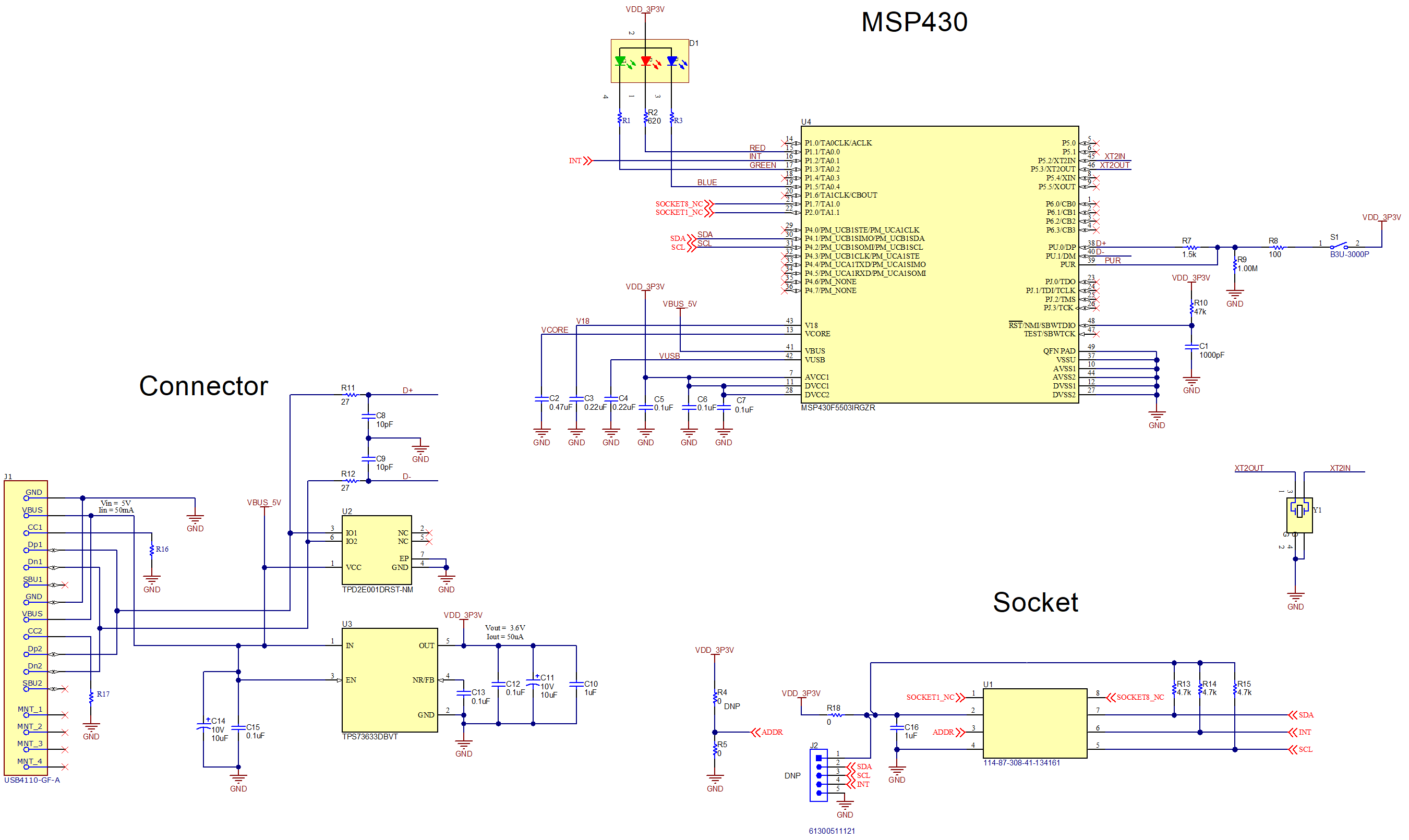
GUID-20211112-SS0I-7PQX-MNH6-GFH1LKNHW9TP-low.pngFigure 4-6 OPTMBEVM Schematic