SBVS482 September   2025 TPS7A14C

PRODUCTION DATA  

  1.   1
  2. 1 Features
  3. 2 Applications
  4. 3 Description
  5. 4 Pin Configuration and Functions
  6. 5 Specifications
    1. 5.1 Absolute Maximum Ratings
    2. 5.2 ESD Ratings
    3. 5.3 Recommended Operating Conditions
    4. 5.4 Thermal Information
    5. 5.5 Electrical Characteristics
    6. 5.6 Typical Characteristics
  7. 6 Detailed Description
    1. 6.1 Overview
    2. 6.2 Functional Block Diagram
    3. 6.3 Feature Description
      1. 6.3.1 Excellent Transient Response
      2. 6.3.2 Global Undervoltage Lockout (UVLO)
      3. 6.3.3 Enable Input
      4. 6.3.4 Internal Foldback Current Limit
      5. 6.3.5 Active Discharge
      6. 6.3.6 Thermal Shutdown
    4. 6.4 Device Functional Modes
      1. 6.4.1 Normal Operation
      2. 6.4.2 Dropout Operation
      3. 6.4.3 Disable Mode
  8. 7 Application and Implementation
    1. 7.1 Application Information
      1. 7.1.1  Recommended Capacitor Types
      2. 7.1.2  Input, Output, and Bias Capacitor Requirements
      3. 7.1.3  Dropout Voltage
      4. 7.1.4  Behavior During Transition From Dropout Into Regulation
      5. 7.1.5  Device Enable Sequencing Requirement
      6. 7.1.6  Load Transient Response
      7. 7.1.7  Undervoltage Lockout Circuit Operation
      8. 7.1.8  Power Dissipation (PD)
      9. 7.1.9  Estimating Junction Temperature
      10. 7.1.10 Recommended Area for Continuous Operation
    2. 7.2 Typical Application
      1. 7.2.1 Design Requirements
      2. 7.2.2 Detailed Design Procedure
      3. 7.2.3 Application Curve
    3. 7.3 Power Supply Recommendations
    4. 7.4 Layout
      1. 7.4.1 Layout Guidelines
      2. 7.4.2 Layout Example
  9. 8 Device and Documentation Support
    1. 8.1 Device Support
      1. 8.1.1 Development Support
      2. 8.1.2 Device Nomenclature
    2. 8.2 Documentation Support
      1. 8.2.1 Related Documentation
    3. 8.3 Receiving Notification of Documentation Updates
    4. 8.4 Support Resources
    5. 8.5 Trademarks
    6. 8.6 Electrostatic Discharge Caution
    7. 8.7 Glossary
  10. 9 Revision History
  11. 10Mechanical, Packaging, and Orderable Information
    1. 10.1 Mechanical Data

Typical Characteristics

at operating temperature TJ = 25°C, VOUT(NOM) = 0.8V, VIN = VOUT(NOM) + 0.1V, VBIAS = VOUT(NOM) + 1.4V, IOUT = 1mA, VEN = VIN, CIN = 4.7µF, COUT = 4.7µF, and CBIAS = 0.47µF (unless otherwise noted)

TPS7A14C Output Voltage Accuracy vs VIN
 
Figure 5-1 Output Voltage Accuracy vs VIN
TPS7A14C Output Voltage Accuracy vs IOUT
 
Figure 5-3 Output Voltage Accuracy vs IOUT
TPS7A14C VBIAS Dropout Voltage vs IOUT
 
Figure 5-5 VBIAS Dropout Voltage vs IOUT
TPS7A14C VBIAS Input Current vs VBIAS
IOUT = 1A
Figure 5-7 VBIAS Input Current vs VBIAS
TPS7A14C VBIAS Shutdown IQ vs VBIAS
IOUT = 0A, VIN = 1V
Figure 5-9 VBIAS Shutdown IQ vs VBIAS
TPS7A14C Enable Threshold vs Temperature
 
Figure 5-11 Enable Threshold vs Temperature
TPS7A14C VBIAS UVLO vs Temperature
 
Figure 5-13 VBIAS UVLO vs Temperature
TPS7A14C Start-Up With VIN Before VBIAS and VEN
tr = 1μs
Figure 5-15 Start-Up With VIN Before VBIAS and VEN
TPS7A14C Start-Up With VIN and VEN Before VBIAS
tr = 1μs
Figure 5-17 Start-Up With VIN and VEN Before VBIAS
TPS7A14C Line Transient From 1V to 2.2V
tr = tf = 10μs, IOUT = 500mA
Figure 5-19 Line Transient From 1V to 2.2V
TPS7A14C Load Transient From 100μA to 1A
tr = tf = 1μs, COUT = 9μF
Figure 5-21 Load Transient From 100μA to 1A
TPS7A14C Load Transient From 100μA to 1A
tr = tf = 20μs, COUT = 9μF
Figure 5-23 Load Transient From 100μA to 1A
TPS7A14C PSRR vs Frequency and
                            VIN – VOUT
COUT = 4.7μF, IOUT = 1A
Figure 5-25 PSRR vs Frequency and VIN – VOUT
TPS7A14C PSRR vs Frequency and
                            IOUT
COUT = 4.7μF, VOUT = 0.8V, VIN = 1V
Figure 5-27 PSRR vs Frequency and IOUT
TPS7A14C PSRR vs Frequency and
                            VBIAS – VOUT
CBIAS = 0μF, COUT = 4.7μF, IOUT = 500mA
Figure 5-29 PSRR vs Frequency and VBIAS – VOUT
TPS7A14C Output Voltage Accuracy vs VBIAS
 
Figure 5-2 Output Voltage Accuracy vs VBIAS
TPS7A14C VIN Dropout Voltage vs IOUT
 
Figure 5-4 VIN Dropout Voltage vs IOUT
TPS7A14C VBIAS Input Current vs VBIAS
 
Figure 5-6 VBIAS Input Current vs VBIAS
TPS7A14C VIN Shutdown IQ vs VIN
IOUT = 0mA
Figure 5-8 VIN Shutdown IQ vs VIN
TPS7A14C VOUT Foldback Current Limit vs Output Current
 
Figure 5-10 VOUT Foldback Current Limit vs Output Current
TPS7A14C VIN UVLO vs Temperature
 
Figure 5-12 VIN UVLO vs Temperature
TPS7A14C Start-Up With VBIAS Before VIN
tr = 1μs
Figure 5-14 Start-Up With VBIAS Before VIN
TPS7A14C Start-Up With VIN and VBIAS Before VEN
tr = 1μs
Figure 5-16 Start-Up With VIN and VBIAS Before VEN
TPS7A14C Line Transient From 1V to 2.2V
tr = tf = 10μs, IOUT = 1mA
Figure 5-18 Line Transient From 1V to 2.2V
TPS7A14C Line Transient From 1V to 2.2V
tr = tf = 10μs, IOUT = 1A
Figure 5-20 Line Transient From 1V to 2.2V
TPS7A14C Load Transient From 10mA to 500mA
tr = tf = 1μs, COUT = 9μF
Figure 5-22 Load Transient From 10mA to 500mA
TPS7A14C Load Transient From 10mA to 500A
tr = tf = 20μs, COUT = 9μF
Figure 5-24 Load Transient From 10mA to 500A
TPS7A14C PSRR vs Frequency and
                            VIN - VOUT
COUT = 9μF, IOUT = 1A
Figure 5-26 PSRR vs Frequency and VIN - VOUT
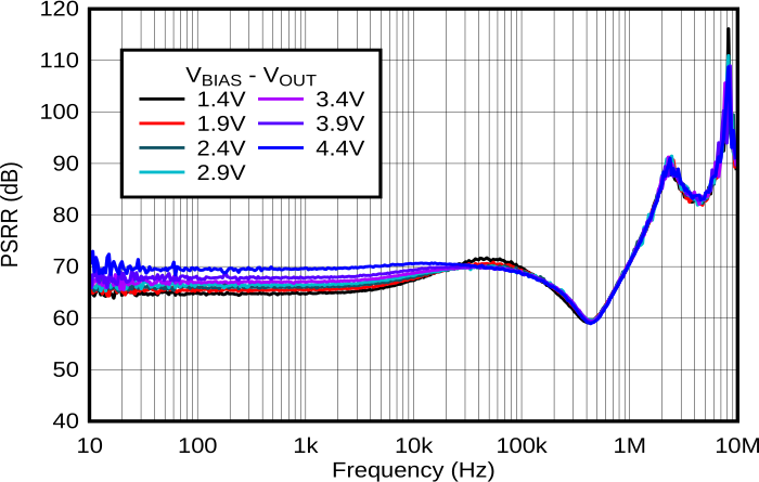
TPS7A14C PSRR vs Frequency and
                            VBIAS – VOUT
CBIAS = 0μF, COUT = 4.7μF, IOUT = 1mA
Figure 5-28 PSRR vs Frequency and VBIAS – VOUT
TPS7A14C Output Noise vs Frequency
                        and IOUT
VOUT = 0.8V
Figure 5-30 Output Noise vs Frequency and IOUT