SCEU025
May 2022
Trademarks
1
CDCBT1001EVM Evaluation Module
1.1
Evaluation Module Contents
1.2
Resources
2
Setup
2.1
Connection Diagram
2.2
Power Supplies
2.3
Input Clock
2.4
Output Clock
3
Schematic
4
Board Structure
4.1
PCB Layer Stack-Up
4.2
PCB Layout
5
Bill of Materials
3
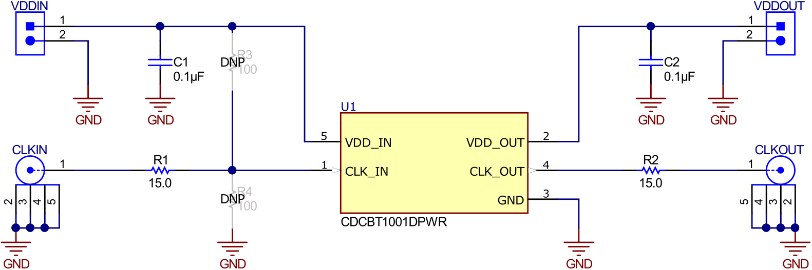
Schematic
Figure 3-1
shows the CDCBT1001EVM schematic.
Figure 3-1
CDCBT1001EVM Schematic