SLAA732A February 2017 – April 2021 PGA460 , PGA460-Q1
4.3 Driver Selection
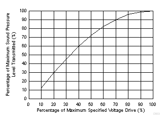
Transducers require a sinusoidal or square wave voltage driver to properly excite the piezoelectric membrane for oscillation at the specified resonant frequency. Because the wide variety of air-coupled transducers of the open and closed-top types, maximum drive voltage specifications typically range between 5 VPP to 200 VPP. The driving voltage specification is important to consider when wanting to maximize the amount of sound pressure level (SPL) generated for long-range measurements. SPL is defined as the logarithmic measure of the effective or RMS sound pressure of a sound relative to the threshold of hearing reference value, measured in decibels (dB). At the maximum driving voltage specification, the amount of SPL a transducer is able to generate is saturated, such that driving a transducer beyond the maximum driving specification will not yield in any additional gains. Figure 4-2 shows the typically relationship between driving voltage and transmittable SPL.
 Figure 4-2 Voltage Driver Versus Sound Pressure Level
To generate a large driving voltage averaging 100 VPP for closed-top transducers, a single-ended or center-tap transformer is typically paired with the transducer, such that the primary-to-secondary turns ratio acts as a times ten multiplier. This ratio is a common turns ratio assuming a PGA460 supply voltage of 6 to 18 V DC. The transformer driver mode enables a low-voltage DC reference to be amplified at the secondary as a sinusoidal waveform. If a smaller driving voltage averaging 10 VPP is required for open-top transducers, the transformer can be replaced with a direct driver using either a half-bridge or full-bridge driver configuration. The direct-driver mode allows the PGA460 device and transducer to reference the same supply voltage without the need for any boost circuitry to excite the transducer. The PGA460 device can only use the mono-static configuration in half-bridge mode. The full-bridge mode is only compatible in the bi-static configuration when using the PGA460 device. Closed-top transducers can be direct driven for short to mid-range applications but will not generate the maximum amount of transmittable SPL for long-range applications.