SLAA732A February 2017 – April 2021 PGA460 , PGA460-Q1
5.5 Threshold
Setting the threshold is the most important feature to optimize, such that no false positives or noise transients trigger the device to calculate distance, amplitude, and width of unwanted signals, but also ensure enough margin is provided to ensure worst-case (weak) reflections from targeted objects can be recognized. By default, and for initial evaluation, TI recommends settings the threshold at 50% of the averaged peak of the return echo.
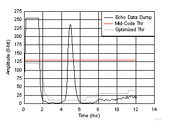
The example in Figure 5-5 shows how the threshold was set for a reliable echo data dump. With the noise floor at a maximum value of 24, and an echo peak at 236, the 50% segment is at 130. The ultrasonic measurement result corresponds to the actual distance calculated and observed on the echo data dump profile.
 Figure 5-5 Threshold Mapping Around Echo Data Dump
The closer the threshold is set to the base of the echo, the more stable and accurate the result will be; however, this also increases the risk for false positives, unless the noise is known to be steady, controlled, or repeatable.