SLAA732A February   2017  – April 2021 PGA460 , PGA460-Q1


  1. 1Trademarks
  2. 2Overview
  3. 3External Performance Factors
    1. 3.1 Range Requirements
    2. 3.2 Detectable Target and Objects
    3. 3.3 Ambient Environment
  4. 4Component Selection
    1. 4.1 Sonar Configuration
    2. 4.2 Transducer Selection
    3. 4.3 Driver Selection
    4. 4.4 Passive Tuning
      1. 4.4.1 Impedance Gain-Phase Analyzer
      2. 4.4.2 Tuning Capacitor
      3. 4.4.3 Damping Resistor
      4. 4.4.4 Tunable Transformer
  5. 5PGA460 Parameters
    1. 5.1 Center Frequency
    2. 5.2 Pulse Count
    3. 5.3 Current Limit
    4. 5.4 Time-Varying Gain and Digital Gain
    5. 5.5 Threshold
  6. 6End-of-Line Calibration
    1. 6.1 Transducer Parameters
      1. 6.1.1 Optimal Frequency and Sound Pressure Level Measurements
        1. 6.1.1.1 Frequency Diagnostic Feature of PGA460
        2. 6.1.1.2 External Microphone
  7. 7Revision History

External Microphone

To monitor both the emitted frequency and SPL of the transducer in amplitude, an external microphone must be used, such as the G.R.A.S. 46BF Free Field Microphone, with an oscilloscope. To convert the peak-to-peak SPL from voltage to dB, use Equation 3 and Equation 4.

Equation 3. SPL Pa = VMeasured mVRMS / 3.4 mV
Equation 4. SPL dB = 20 × log10 (SPL Pa / PO)

where

  • PO is reference sound pressure of 20 µPa

In the example in Figure 6-2, the green waveform represents the driving voltage across the transducer and the purple waveform represents the ultrasonic echo captured by the external microphone at 30 cm. Both the frequency and dB equivalent can be monitored using this method.
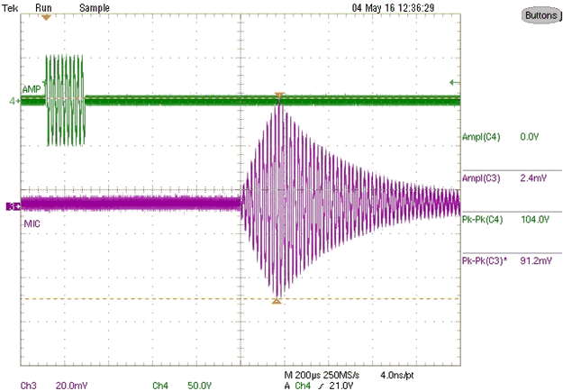
GUID-6F32E4E7-80DD-411E-AC08-BDCF684E0A26-low.gifFigure 6-2 Sound Pressure Level as Voltage Equivalent