SLAA870 February 2019 AFE7422 , AFE7444
-
Evaluating the frequency hopping capability of the AFE74xx
- Trademarks
- 1 Introduction
- 2 Phase Coherency vs Phase Continuity
- 3 AFE74xx Architecture
- 4 Frequency Hopping Methods
- 5 NCO Frequency Resolution Versus Hop Time
- 6 Fast Frequency Hopping With the Load and Switch
- 7 Register Addresses
- 8 References
4.2.2.2 Software Configuration
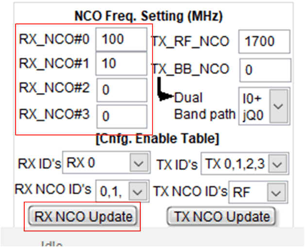
To configure the AFE74xx receiver NCOs to switch using the GPIO pins, follow the normal AFE74xx GUI bringup procedure with one difference. Before pressing set mode after selecting a mode, navigate to the Advanced tab in the GUI, and observe the NCO Freq Setting section at the bottom left of the window. The RX_NCO# fields are where each NCO is programmed. NCO#0, NCO#1, and NCO#2 are the three NCOs available in the single band DDC. NCO#3 is the single NCO found in the second DDC and is only available in dual-band mode. RX IDs determine the ADC in which the NCOs are programmed. RX NCO IDs enable the NCOs to be programmed.
In the example shown in Figure 24, NCO0 is programmed to 100 MHz and NCO1 is programmed to 10 MHz. Select NCO IDs 0,1 because only NCO0 and NCO1 are used. For RX ID, select RX 0 because this experiment requires programming only one ADC. After entering the desired RX NCO values, press NCO update to automatically update the corresponding RX NCO registers.
 Figure 24. Programming RXNCO0 and RXNCO1 to 100 MHz and 10 MHz, Respectively
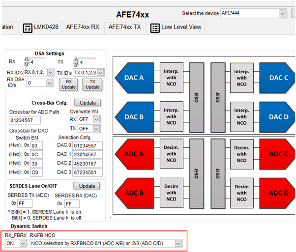
 After programming the RX NCO values, the AFE74xx receivers must be configured to selectively switch NCOs using the GPIO pins. RX NCO selection using the GPIO pins is configured through the AFE74xx in the Advanced tab under the Dynamic Switch section. Select ON under the RX_FBRX drop-down menu. Select NCO selection by RXFBNCO 0/1 (ADC A/B) or 2/3 (ABC C/D) under the RX/FB NCO drop-down menu, as shown in Figure 25.
 Figure 25. Configuring RX NCO Selection Through the GPIO Pins Using the AFE74xx GUI