SLAAE25 May 2021 MSP430FR2355 , MSP430FR2355
5.3 First Stage DC Tracking
A simple a low-pass IIR digital filter is used to track the DC value of the signal after the TIA, and adjust the offset of the second-stage amplification.
A DC tracking filter is illustrated in Figure 5-3.
 Figure 5-3 Tacking Filter Block
Diagram
Figure 5-3 Tacking Filter Block
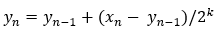
DiagramThis is an IIR filter. The working of this filter is best understood intuitively. The filter adds a small portion of the difference between its input and its last output value to its last output value to form the new output value. It there is a step change in the input, the output changes itself to be the same as the input over a period of time. The rate of change is controlled by the coefficient K. K is worked out by experiment. So, if the input contains an AC and DC component, the coefficient K is made sufficiently small to generate a time constant relative to the frequency of the AC component so that over a length of time the AC will cancel itself out in the accumulation process and the output would only track the DC component of the input.
As shown in Figure 5-4, high frequency noise is filtered out by IIR, and it can track the DC value of ADC data well.
 Figure 5-4 IIR DC Tracking Filter