SLAAE25 May 2021 MSP430FR2355 , MSP430FR2355
3 Single-Chip Design
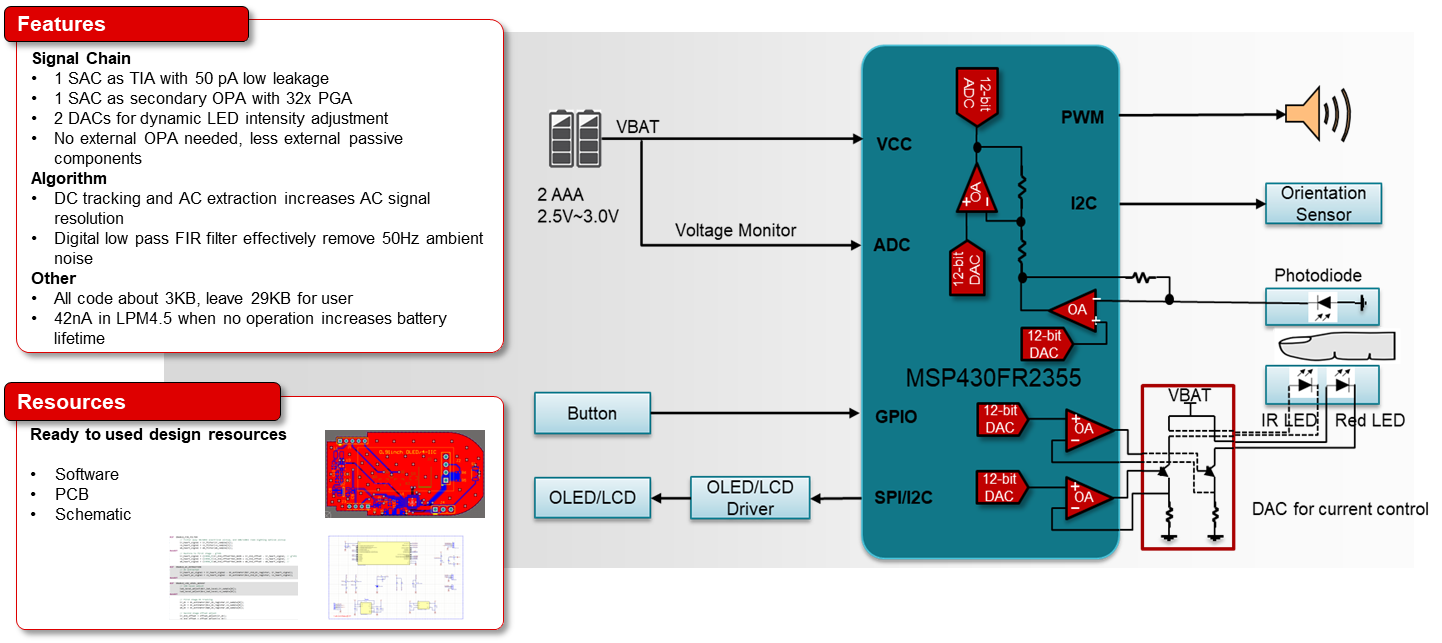
Figure 3-1 shows the proposed block diagram of a single-chip pulse oximeter design using the MSP430FR235x. All four SACs are utilized optimally: two for the LED drive stage (Red and IR) and two for the photodiode signal conditioning (TIA and gain stage). Internal clocks and voltage references are selected to minimize the use of external components thus reducing the overall Bill of Material (BOM) cost as well as the footprint of the design.
 Figure 3-1 Single-Chip Solution for Pulse
Oximeter