SLAAEG7 April 2024 TAC5111 , TAC5111-Q1 , TAC5112 , TAC5112-Q1 , TAC5211 , TAC5212 , TAC5212-Q1 , TAD5112 , TAD5112-Q1 , TAD5212 , TAD5212-Q1
- 1
- Abstract
- Trademarks
- 1Headset Plugs and Connection Diagrams
- 2Example for a Pseudo-Differential (Capacitor-less) Output Configuration
- 3Example for an AC-Coupled (Capacitor) Output Configuration
- 4Flowchart for Pseudo-Differential (Capacitor-less) Output Configuration
- 5Flowchart for AC-Coupled (Capacitor) Output Configuration
- 6Summary
- 7References
1.1 Part I: Pseudo-Differential (Capacitor-less) Headset Output Configuration
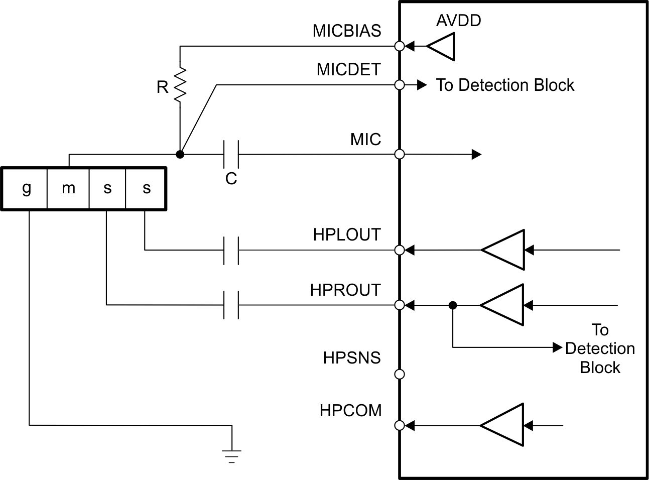
Figure 1-3 shows one configuration of the device that enables detection and determination of headset type when a pseudo-differential (capacitor-less) stereo headphone output connection is used. Note that for best results, it is recommended to select a MICBIAS value as high as possible, and to program the output driver common-mode level at a 1.6-V or 1.5-V level.
 Figure 1-3 Device With a
Pseudo-Differential (Capacitor-less) Headset Output Connection
Figure 1-3 Device With a
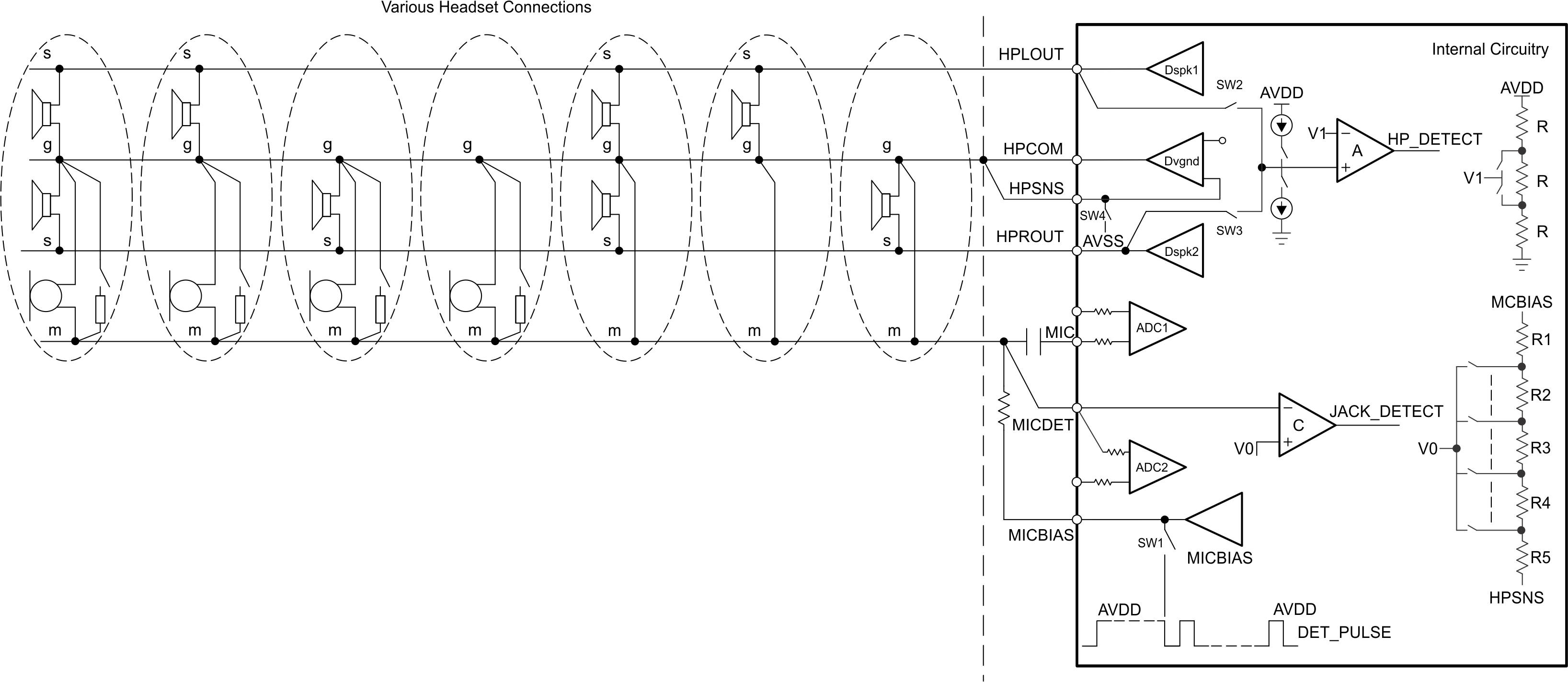
Pseudo-Differential (Capacitor-less) Headset Output ConnectionFigure 1-4 demonstrates the internal circuitry that implements the detection logic. The two comparators in this figure is used for headphone and jack detection.
 Figure 1-4 Circuit Diagram of Detection Scheme for Capacitor-less Interface