SLAU599B August 2015 – July 2021
- Trademarks
- 1Getting Started
-
2Hardware
- 2.1
Hardware Features
- 2.1.1 BoosterPack Plug-in Module Pinout
- 2.1.2 TI OPT3001 Light Sensor
- 2.1.3 TI TMP006 Temperature Sensor
- 2.1.4 Servo Motor Connector
- 2.1.5 3-Axis Accelerometer
- 2.1.6 RGB Multicolor LED
- 2.1.7 Piezo Buzzer
- 2.1.8 Color 128x128-Pixel TFT LCD Display
- 2.1.9 Microphone
- 2.1.10 2-Axis Joystick With Pushbutton
- 2.1.11 User Pushbuttons
- 2.2 Power
- 2.3 Design Files
- 2.4 Hardware Change log
- 2.1
Hardware Features
- 3Software Examples
- 4Additional Resources
- 5Schematics
- 6Revision History
3.5.2 Operation
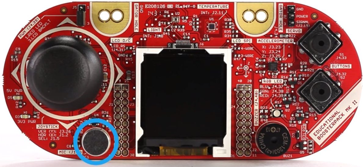
This demo visualizes 512-point real FFT results calculated from audio samples gathered in real-time from the onboard microphone of the Educational BoosterPack plug-in module MKII (see Figure 3-5). The demo uses the real FFT function contained in the CMSIS DSP Software Library.
 Figure 3-5 Microphone
The program begins by using the MSP432 built-in ADC14 module to sample audio signal at 8 KHz from the microphone on the Educational BoosterPack plug-in module MKII. To achieve seamless data processing, the MSP432 built-in DMA module is set up in Ping-Pong mode to alternate between two data buffers. This allows the ADC14 module to continue gathering audio data into one buffer, while the MSP432 runs the FFT algorithm on the other buffer.
When the DMA module completes data transfers from ADC14 results to one of the 512 length data buffers, an interrupt is triggered to wake the MSP432 from LPM0 sleep mode to initiate the 512-point real FFT calculation. The resulting frequency bin data is displayed in a bar graph on the BoosterPack plug-in module's colored 128x128 dot-matrix LCD using MSP Graphics Library.
Try generating a pure tone ranging from 1 Hz to 4000 Hz and see if the demo shows the correct frequency.