SLLA565 September 2021 TUSB1044
2.1.3 UEQ[1:0] and DEQ[1:0]
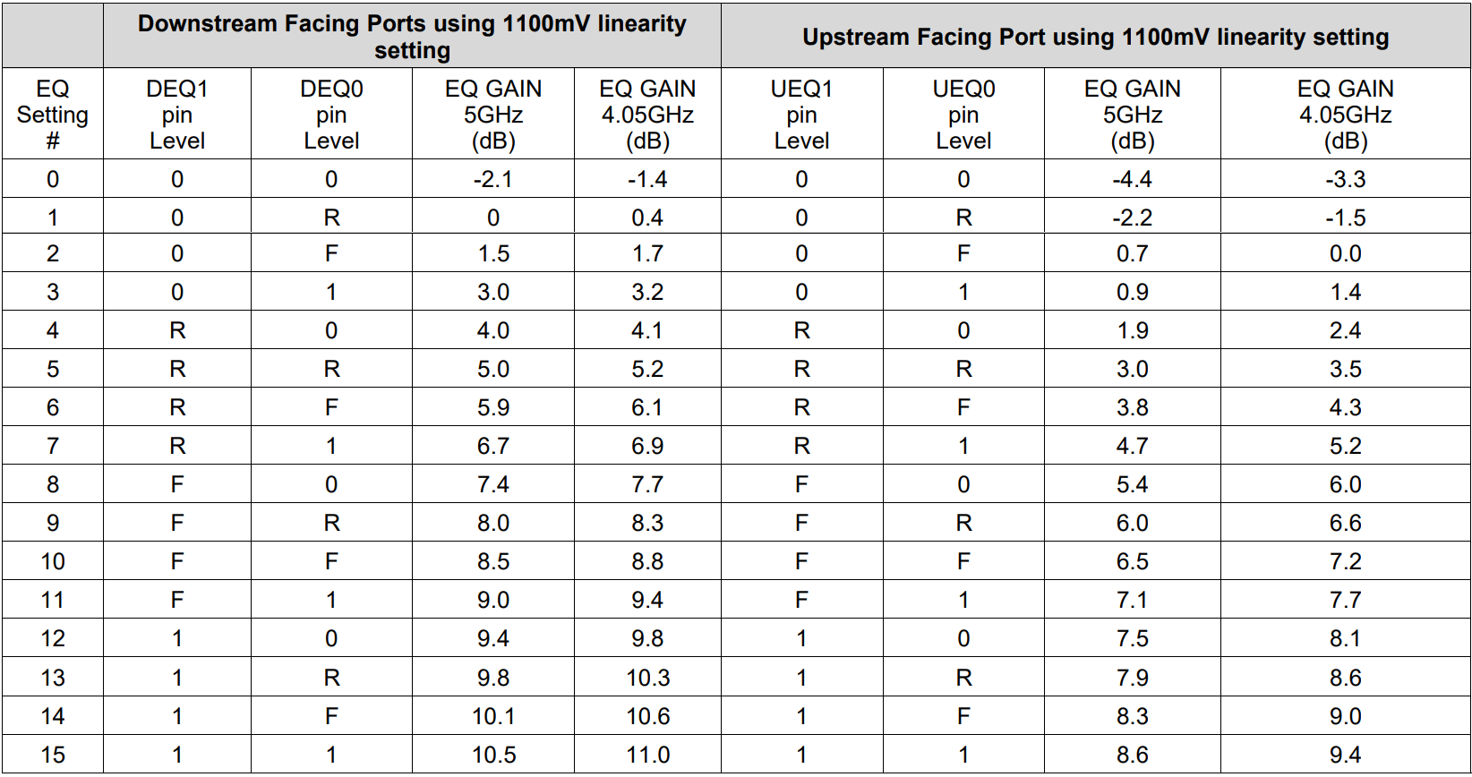
The TUSB1044 receiver equalization (EQ) is to compensate for channel insertion loss and inter-symbol interference in the system. The receiver overcomes these losses by attenuating the low-frequency components of the signals with respect to the high-frequency components. Each channel has a receiver equalizer with selectable gain settings as shown in Table 2-4. Set equalization control for upstream and downstream facing ports using the UEQ[1:0], and DEQ[1:0] pins, respectively.
Figure 2-1 shows the TUSB1044 equalization settings.

Figure 2-1 TUSB1044 Equalization Settings
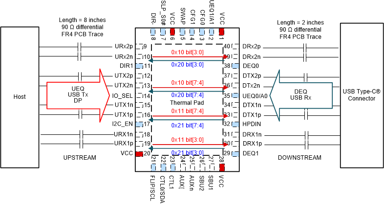
Using the given trace lengths and data rate referring to the Figure 2-2 example, the method to select the equalization values for upstream and downstream EQ is to select the closest EQ gain value available to match the trace loss as follows:
- Host to TUSB1044 trace length 8 in (7-dB loss at 5 GHz). UEQ setting of 7.1 dB.
- TUSB1044 to connector trace length 2 in (1.7-dB loss at 5 GHz). DEQ setting of 3 dB

Figure 2-2 Reference Block Diagram for TUSB1044 Equalization Control
In the I2C mode, the equalization settings for each receiver can be independently controlled through I2C registers. For this reason, all of the equalization pins (UEQ[1:0] and DEQ[1:0]) can be left unconnected. If a different I2C slave address is desired, UEQ1/A1 and UEQ0/A0 pins should be set to a level other than ‘F’ which produces the desired I2C slave address.