SLLA624 October 2023 ISOM8110 , ISOM8110-Q1 , ISOM8111 , ISOM8111-Q1 , ISOM8112 , ISOM8112-Q1 , ISOM8113 , ISOM8113-Q1 , ISOM8115 , ISOM8115-Q1 , ISOM8116 , ISOM8116-Q1 , ISOM8117 , ISOM8117-Q1 , ISOM8118 , ISOM8118-Q1 , ISOM8600 , ISOM8610 , ISOM8710 , ISOM8711
Overview
Traditional optocouplers provide isolation using an LED and a photodiode. LED-based optocouplers are certified according to IEC 60747-5-5, which is the international optocoupler standard that has been active since 2007. Updates to the current (2.0) edition were released in 2020.TI’s new opto-emulators use silicon dioxide (SiO2) isolation technology to provide isolation. As a result, opto-emulators and digital isolators are certified according to a different standard (IEC 60747-17) that became the international digital isolator standard in September 2020.
The new digital isolator standard (IEC 60747-17) has many test requirements that are more stringent and detailed than the optocoupler standard (IEC 60747-5-5). Opto-emulators and digital isolators are evaluated to a criterion that provides a comprehensive understanding of device performance and capability.
IEC 60747-17 versus IEC 60747-5-5 at a glance
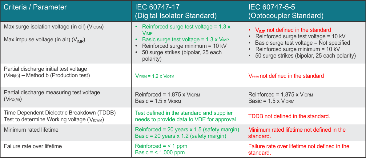
Figure 1 provides an overview comparing the digital isolator standard (IEC 60747-17) and the optocoupler standard (IEC 60747-5-5).For additional information on IEC 607 47-17 specifications, see [FAQ] High-Voltage Isolation Parameters.
 Figure 1 Isolation Standard Comparison
- IEC 60747-17 versus IEC 60747-5-5
Figure 1 Isolation Standard Comparison
- IEC 60747-17 versus IEC 60747-5-5Details
Maximum impulse voltage (VIMP)
To differentiate between isolation performance in oil vs in air, IEC 60747-17 specifies that the isolation performance of a digital isolator is tested in both oil (VIOSM) and in air (VIMP). Whereas the optocoupler standard, IEC 60747-5-5, does not specify both parameters.
When the device is tested in oil, the possibility of arcing across the package is negated. Isolation performance in an application is not accurately represented without also testing in air (VIMP). The digital isolator specification defines VIMP for an in air isolation test and VIOSM for isolation test in oil. Whereas the optocoupler specification only specifies VIOSM and does not specify if the device is tested in air or oil.
When the device is tested in oil, the possibility of arcing across the package is negated. Isolation performance in an application is not accurately represented without also testing in air (VIMP). The digital isolator spec defines VIMP for an in air isolation test and VIOSM for isolation test in oil. The optocoupler specification only specifies VIOSM and does not specify if the device is tested in air or oil.
IEC 60747-17 defines VIMP as a benefit to the customer to understand in system performance of a digital isolator. See the Insulation Specifications section of the data sheet for VIMP and other IEC 60747-17 related specifications, and see [FAQ] What is Maximum Impulse Voltage (VIMP) for more information related to VIMP.
The following sections show the key differences between the two standards:
Partial discharge test (production test): Method B testing
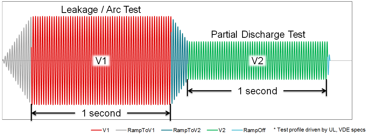
 Figure 2 Method B Test Waveform
Partial Discharge of Digital Isolators and Opto-emulators are testing using the Method b testing. An example of a Method b1 test waveform is shown in Figure 2 which is defined by the IEC 60747-17 standard. Where V1 is the voltage that leakage testing is performed at and V2 is the voltage that partial discharge testing is performed at.
Isolation parameters are tested in production following the method B testing. Digital isolation devices are tested in production using the following procedure.
- One second at 1.2 ×
VIOTM followed by one second at 1.875 × VIORM.
- Optocouplers only specify testing at one second at 1.875 × VIORM.
- For example, for an isolator
rated for 3.75 kVRMS isolation is test at:
- Reinforced isolators are tested at 6.36 kVPK AC 50 Hz and 60 Hz followed by 1.33 kVPK AC 50 or 60 Hz.
- Optocouplers are only required to test at 1.875 × VIORM with no initial stress level voltage (Vini) of one second at 1.2 × VIOTM.
The digital isolator standard contains more stringent test conditions.
Time dependent dielectric breakdown (TDDB) testing
TDDB testing identifies life expectancy associated with the dielectric material of an isolator. TDDB is accelerated by applying an electric field across the dielectric at an increased temperature.
- TI runs TDDB testing across hundreds of units.
- The optocoupler standard does not require TDDB lifetime testing.
For more details on TDDB testing methodology, see Enabling high voltage signal isolation quality and reliability.
Conclusion
Due to rigorous testing through IEC 60747-17, TI has a high confidence in the longevity, robustness, and reliability of the isolation barrier. The additional specifications of IEC 60747-17 also can provide a picture of device performance and insulation capability over IEC 60747-5-5, which is the traditional optocoupler standard.