SLLU166A June 2012 – September 2022
4 ISO154xEVM Layout
Figure 4-1 shows the top-layer routing of the ISO154xEVM.
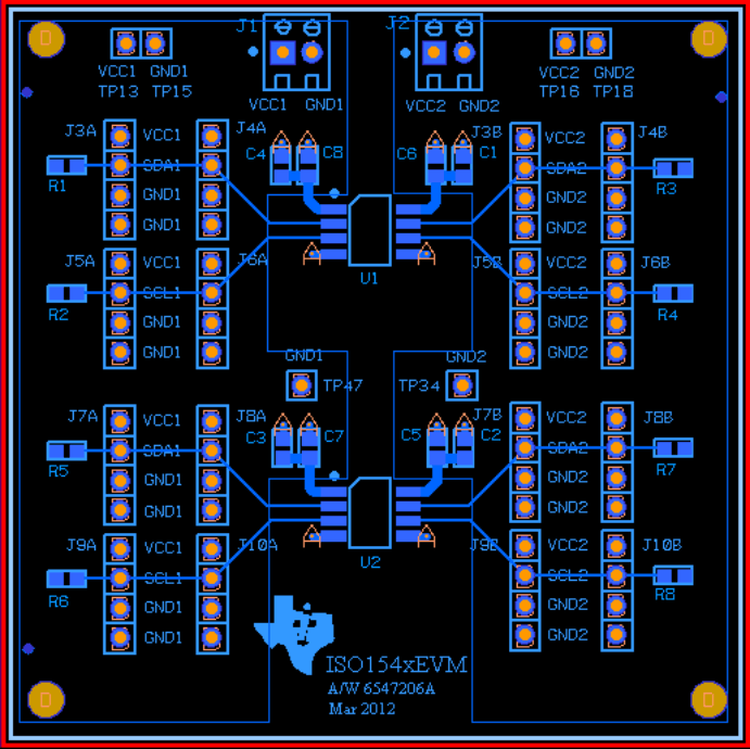 Figure 4-1 ISO154xEVM Top-layer Routing
Figure 4-2 shows the bottom-layer ground planes (shaded areas).
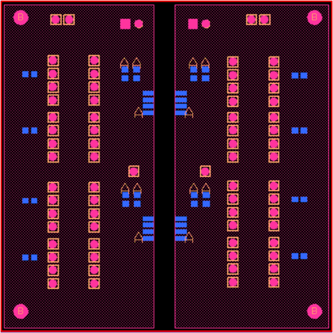 Figure 4-2 ISO154xEVM Bottom-layer Ground Planes