SLOA207A November 2014 – November 2021 DRV2603 , DRV2604 , DRV2604L , DRV2605 , DRV2605L , DRV2624 , DRV2625
3.1 Braking
Braking is one of the most important actions required for sharp, crisp haptic effects. Without it, the actuator will continue to vibrate until its own mechanical damping puts it to rest, which is actuator specific and can last hundreds of milliseconds.
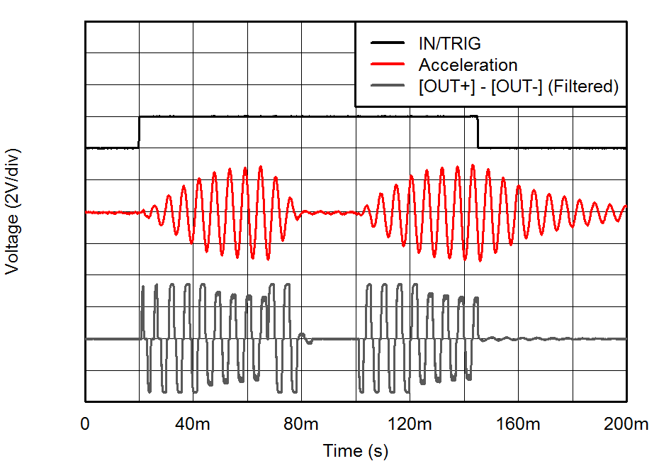
The ability to brake an actuator resides on accurately driving it in the opposite direction with the optimum strength and for the optimum time. Such a result can be attained by careful manual tuning, however, since the properties of the actuator change constantly due to temperature, aging, mechanical compression, and so forth, is not possible for an open-loop manually tuned system to operate optimally all the time. The alternative method is by using a closed-loop system, such as the one provided in TI's DRV260x and DRV262x haptic driver device families, that monitors the status of the actuator and reacts with the appropriate strength and for the appropriate time, dynamically adjusting to any change and, therefore, optimizing the braking performance. Figure 3-1 shows a typical performance of a click with and without braking in a closed-loop system.
 Figure 3-1 LRA Click
With and Without Braking
Figure 3-1 LRA Click
With and Without BrakingFor the case of ERM actuators, the ability to brake requires voltage to be applied in the opposite direction. For this reason, braking is not possible if using the typical FET implementation, since it can only provide voltage in one direction. Braking is possible, however, if an H-bridge or other differential output solution is used (such as TI's DRV8601, DRV2603, DRV2604, DRV2605, DRV2605L, DRV2624 and DRV2625 devices).
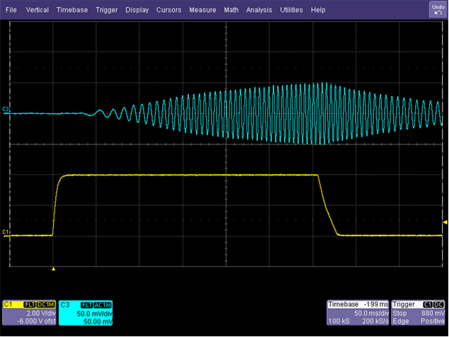
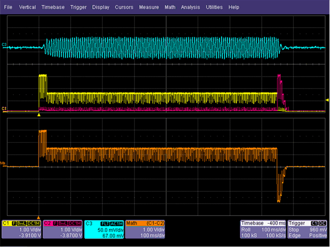
BLDC modules have a similar limitation to the ERM FET implementation, since it is not possible to reverse the direction of the BLDC actuator. A typical BLDC module alert effect is shown in Figure 3-2. Figure 3-3 is shown for comparison.
 Figure 3-2 Typical BLDC Module Alert Effect
 Figure 3-3 Typical ERM Alert Effect
With TI's Closed-Loop Driver