SLOA207A November 2014 – November 2021 DRV2603 , DRV2604 , DRV2604L , DRV2605 , DRV2605L , DRV2624 , DRV2625
4 Actuator Comparison
Measurements between ERMs, LRAs and BLDCs were taken for comparison. ERM and LRA actuators were driven with the DRV2605 driver from TI. The BLDC module was powered by a simple FET circuit, as shown in Figure 4-1. This data is representative of all DRV260x and DRV262x devices, but all measurements were taken with the DRV2605.
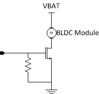 Figure 4-1 Circuit for Driving the BLDC
Alert waveforms comparing 4 different actuators are shown in Figure 4-2, Figure 4-3, Figure 4-4, and Figure 4-5.
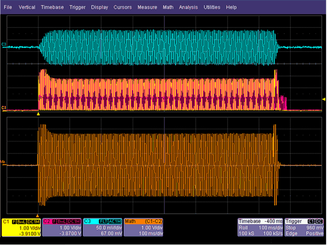 Figure 4-2 LRA Alert Waveform - AAC1030
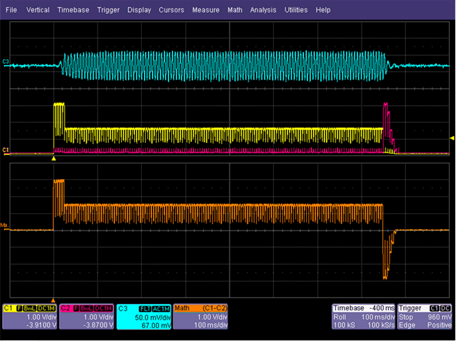 Figure 4-4 ERM Alert Waveform - NRS2574i
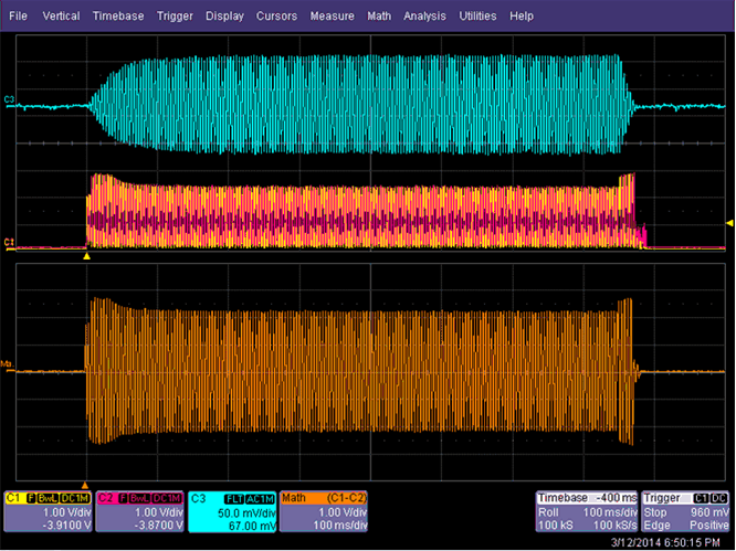 Figure 4-3 LRA Alert Waveform - SEMCO0832
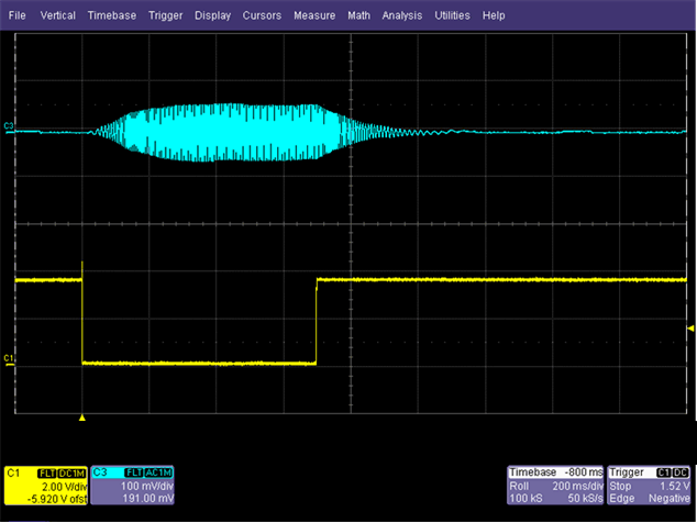 Figure 4-5 BLDC Alert Waveform
Triple click waveforms comparing 3 different actuators are shown in Figure 4-6, Figure 4-7, and Figure 4-8 (BLDC modules cannot do clicks).
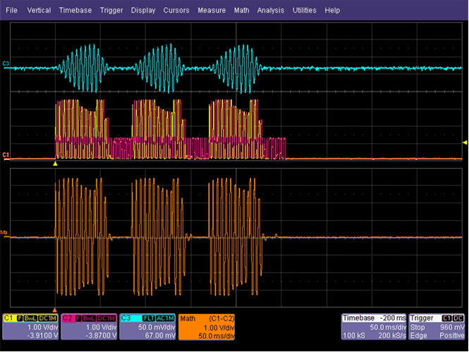 Figure 4-6 LRA Triple Click Waveform - AAC1030
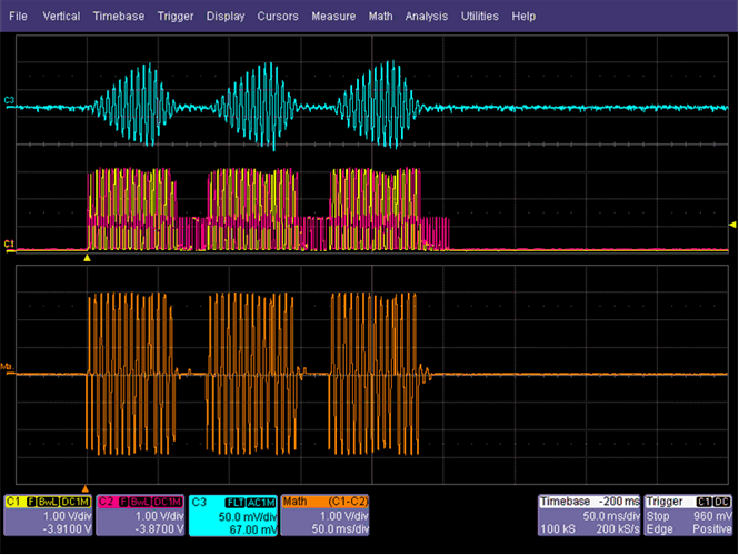 Figure 4-7 LRA Triple Click Waveform - SEMCO0832
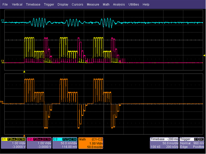 Figure 4-8 ERM Triple Click Waveform - NRS2574i
Current consumption versus battery voltage, and acceleration versus battery voltage are shown in Figure 4-9, Figure 4-10, Figure 4-11, and Figure 4-12 (measurements related to ERM and LRA were taken using the DRV2605 driver from TI). Since in some instances the acceleration used as comparison is not attainable due to actuator or system limitations, the acceleration plots are also provided.
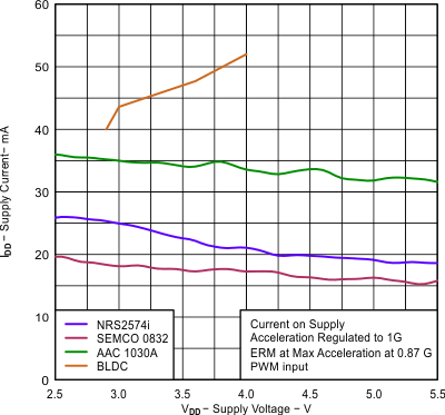 Figure 4-9 Current Consumption Comparison With 1 G of Acceleration
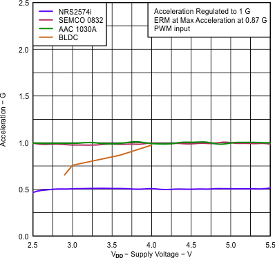 Figure 4-10 Acceleration Comparison With 1 G of Acceleration
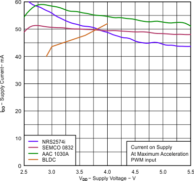 Figure 4-11 Current Consumption Comparison With Maximum Acceleration
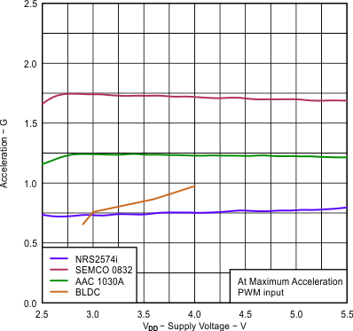 Figure 4-12 Acceleration Comparison With Maximum Acceleration
Table 4-1 shows the comparson of start-time, brake-time, and acceleration performance. Note that when it comes to start-time and brake-time, smaller is better.
| ACTUATOR/DRIVER | BLDC/FET | NRS2571i/DRV2605 | AAC1030/DRV2605 | SEMCO0832/DRV2605 |
|---|---|---|---|---|
| Start-Time [ms] | 400 | 47 | 43 | 93 |
| Brake-Time [ms] | 350 | 37 | 17 | 24 |
| Maximum Acceleration [g] | 0.95 | 0.75 | 1.25 | 1.75 |
| Efficiency [g/W] | 4.85 | 3.95 | 6.25 | 9.71 |