SLUAA81A October 2020 – February 2022 BQ769142 , BQ76922 , BQ76942 , BQ76952
3 Stand-Alone Balancing Algorithm and Settings
The BQ769x2 devices have cell balancing disabled and autonomous mode is selected by default. Figure 3-1 shows the Balancing Configuration register in the Battery Management Studio software. To enable stand-alone cell balancing, the [CB_CHG] or [CB_RLX] bits can be set.
 Figure 3-1 Balancing Configuration
Register
Figure 3-1 Balancing Configuration
RegisterCharge versus Relax - autonomous balancing can be allowed during charging by [CB_CHG], or in a relaxed condition by setting [CB_RLX], or both. If [CB_CHG] is set, autonomous balancing is allowed while the CC1 Current is above Settings:Current Thresholds:Chg Current Threshold. If [CB_RLX] is set, autonomous balancing is allowed while the current is below Settings:Current Thresholds:Chg Current Threshold and above the negative of Settings:Current Thresholds:Dsg Current Threshold. The device evaluates the conditions for continuing balancing every Cell Balance Interval. For example, if the device is configured to avoid balancing during charge, and while balancing the pack begins charging, balancing will continue until the interval timer expires before it is disabled.
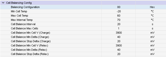
There are multiple parameters shown in the Battery Management Studio Data Memory window below. The temperature parameters Min Cell Temp, Max Cell Temp, and Max Balance Current set allowable temperature limits for cell balancing. The device will disable balancing (both autonomous and host-controlled) if the temperatures violate the limits set by these parameters. Cell Balance Max Cells limits the number of cells that can be balanced simultaneously in autonomous mode (this parameter is ignored in host-controlled mode). This can be very helpful to limit the power dissipation during balancing.
 Figure 3-2 Default Cell Balancing Config Settings
in BQStudio
Figure 3-2 Default Cell Balancing Config Settings
in BQStudioIf autonomous balancing during charge is enabled, the device will allow balancing if the minimum cell voltage is above Cell Balance Min Cell V (Charge) and the difference between the maximum and minimum cell voltages is greater than Cell Balance Min Delta (Charge). Similarly, if autonomous balancing during relax is enabled, the device will allow balancing if the minimum cell voltage is above Cell Balance Min Cell V (Relax) and the difference between the maximum and minimum cell voltages is greater than Cell Balance Min Delta (Relax). While balancing during relax, when the device re-evaluates the cell status at the end of each timer interval, it will cease balancing if all cell voltages are within Cell Balance Stop Delta (Relax) of the minimum cell voltage. This Cell Balance Stop Delta reduces the risk of overbalancing a higher voltage cell to slightly below the minimum voltage cell, and thereby slowly draining the pack. Operation while balancing during charge is similar, instead using the Cell Balance Stop Delta (Charge) configuration value. The Cell Balance Stop Delta parameters should be set to a slightly lower level than the Cell Balance Min Delta parameters, then the device will have a hysteresis that delays restarting balancing until the level of imbalance again exceeds the higher Cell Balance Min Delta level.
Let’s look at a simple example with 4 cells where cell balancing is enabled during charge ([CB_CHG] is set). If Cell Balnance Min Cell V (Charge) = 3900 mV, Cell Balance Min Delta (Charge) = 40 mV, and Cell Balance Stop Delta (Charge) = 20 mV. As the cells charge, we reach a point where Cell1 = 3900 mV, Cell2 = 3940 mV, Cell 3 = 3910 mV, and Cell 4 = 3930 mV. At this point, balancing will start because Cell2 is above the Cell Balance Min Delta and all cells are above the Cell Balnance Min Cell V. Once balancing starts, Cell 4 will also balance because it is above the Cell Balance Stop Delta.
NORMAL versus SLEEP Mode - The BQ769x2 device can also be configured to avoid autonomous balancing while in SLEEP mode by clearing the Balancing Configuration[CB_SLEEP] configuration bit. The device can also be prevented from entering SLEEP mode while balancing if the Balancing Configuration[CB_NOSLEEP] bit is set. The functionality based on these bits is described in the table below.
| CB_SLEEP | CB_NOSLEEP | Description |
|---|---|---|
| 0 | 0 | Cell balancing is not allowed to occur while in SLEEP mode. If balancing were active when the device entered SLEEP mode, balancing would stop at the end of the present Cell Balance Interval and could not restart until the device returned to NORMAL mode. |
| 0 | 1 | This setting is not allowed. When CB_NOSLEEP is set, CB_SLEEP should also be set. |
| 1 | 0 | Cell balancing is allowed to begin and continue while the device is in SLEEP mode |
| 1 | 1 | If the device is in SLEEP mode and cell balancing is deemed necessary, the device will exit SLEEP mode to begin balancing. The device is prevented from re-entering SLEEP mode while balancing is active. |