SLUUCB9A June 2020 – January 2021 BQ25730 , BQ25731
2.3 Equipment Setup
Use the following guidelines to set up the equipment:
- Set power supply #1 for 10-V DC, 5-A current limit and then turn off the supply.
- Connect the output of power supply #1 in series with a current meter to J1 (VIN and PGND).
- Connect a voltage meter across J1 (VIN) and J1 (PGND).
- Connect load #1 in series with a current meter to J6 (VSYS and PGND). Connect a voltage meter across J6 (VSYS and PGND). Set 1 A at the constant current mode. Turn off load #1.
- Connect Load #2 in series with a current meter to J5 (VBAT and PGND). Connect a voltage meter across J5 (VBAT and PGND). Set 7 V at KEPCO load output. Turn off Load #2.
Note:
Add a 47-µF capacitor on the BAT pin when testing without real battery.
- Connect J3 to the EV2400. Connect J3 to the I2C PORT 2 on the EV2400. The connections are shown in Figure 2-1.
 The picture shows the SMBus version EVM connection. For I2C version, move the connector to the I2C port.Figure 2-1 EV2400 Connections
 - Install jumpers using the “factory settings” from Table 1-2.
After completing these steps, the test setup for BMS051 is as shown in Figure 2-2.
") Figure 2-2 Original Test Setup for BMS051 (BQ2573X EVM)
Figure 2-2 Original Test Setup for BMS051 (BQ2573X EVM) - Turn on the computer and power supply #1. Open the BQstudio software.
- Select Charger and click the Next button.
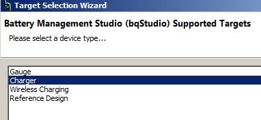
- Select “Charger_1_00_BQ2573x.bqz” on the Select a Target Page.
- After selecting the target device, change “update mode” from “immediate” to “manual”, click “Read Register” and the following interface is presented.
- Select Charger and click the Next button.
 Figure 2-3 BQ2573X Evaluation Software Main Window