SLVA767A September 2016 – December 2016 SN75469 , TPL7407L , TPL9201 , ULN2003A , ULN2003B , ULN2003V12 , ULN2004A , ULQ2003A , ULQ2003A-Q1 , ULQ2004A , ULQ2004A-Q1
3.2 Detailed Design Considerations
When using a peripheral driver for stepper motor driving applications there are a few design considerations that should be highlighted.
- Logic Inputs should be within the acceptable recommended voltage range - see device Electrical Characteristics for further information.
- Output voltages should not exceed the maximum recommended output voltage (VOUT(MAX)) specified for the device. Output voltage and current tolerances vary by device - see device Electrical Characteristics for further information.
- Some devices may require a capacitor on the COM pin - see device Electrical Characteristics for further information.
- The COM pin should be connected to the highest external supply, as this is required to suppress inductive kickback from the motor.
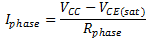
- The current through each motor phase (Iphase) is a function of the supply voltage (VCC), the low-level output voltage (VOL or VCE(sat)) and the phase resistance (Rphase).
- Equation 1 provides the equation for the Relay Current
- See device Electrical Characteristics for the maximum allowable output current (ICE(MAX) or IDS(MAX)) and the low-level output voltage (VOL or VCE(sat))
Equation 1.