SLVA833D October 2016 – May 2021 TPS2660 , TPS2662 , TPS2663
- Trademarks
- 1 Surge Test (IEC 61000-4-5)
- 2 EFuse Solution for Surge Protection
- 3 EFuse Solution Schematic for Surge Protection
- 4 Circuit Performance for Surge Tests
- 5 EFT Test (IEC 61000-4-4)
- 6 EFuse Solution Schematic for EFT protection
- 7 Circuit Performance for EFT Tests
- 8 Power-Fail Test (IEC 61000-4-29)
- 9 EFuse Solution Schematic for Power-Fail Applications
- 10Circuit Performance for Power-Fail Tests
- 11EFT, Surge and Power-Fail Test Setup
- 12Conclusion
- 13References
- 14Revision History
1 Surge Test (IEC 61000-4-5)
The surge test is performed to make sure the system is immune to surges produced by lightning strikes and power system transients such as capacitor bank switching, short circuits and arcing faults. Surge testing is one of the highest energy pulse tests done on the system.
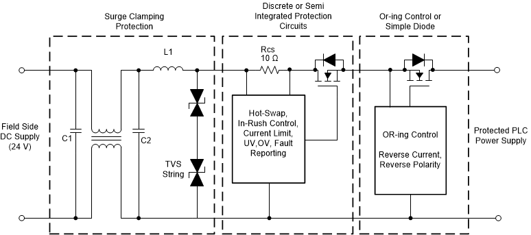
Typical traditional surge and front-end protection circuits used in a PLC system are shown in Figure 1-1. Input side passive components like common mode choke, series inductor and capacitors are used to reduce slew rate of the surge pulse. A string of TVS diodes is used to clamp the surge magnitude to an acceptable level. A series diode or an OR-ing controller with an external FET is used to protect the downstream from negative voltages. Negative voltages are most common either due to miswiring or a negative surge pulse. Discrete or semi-integrated solutions are used for hot-swap, inrush control, monitoring, undervoltage (UV) and overvoltage (OV) protection.
 Figure 1-1 Traditional Input Protection
Circuits
Figure 1-1 Traditional Input Protection
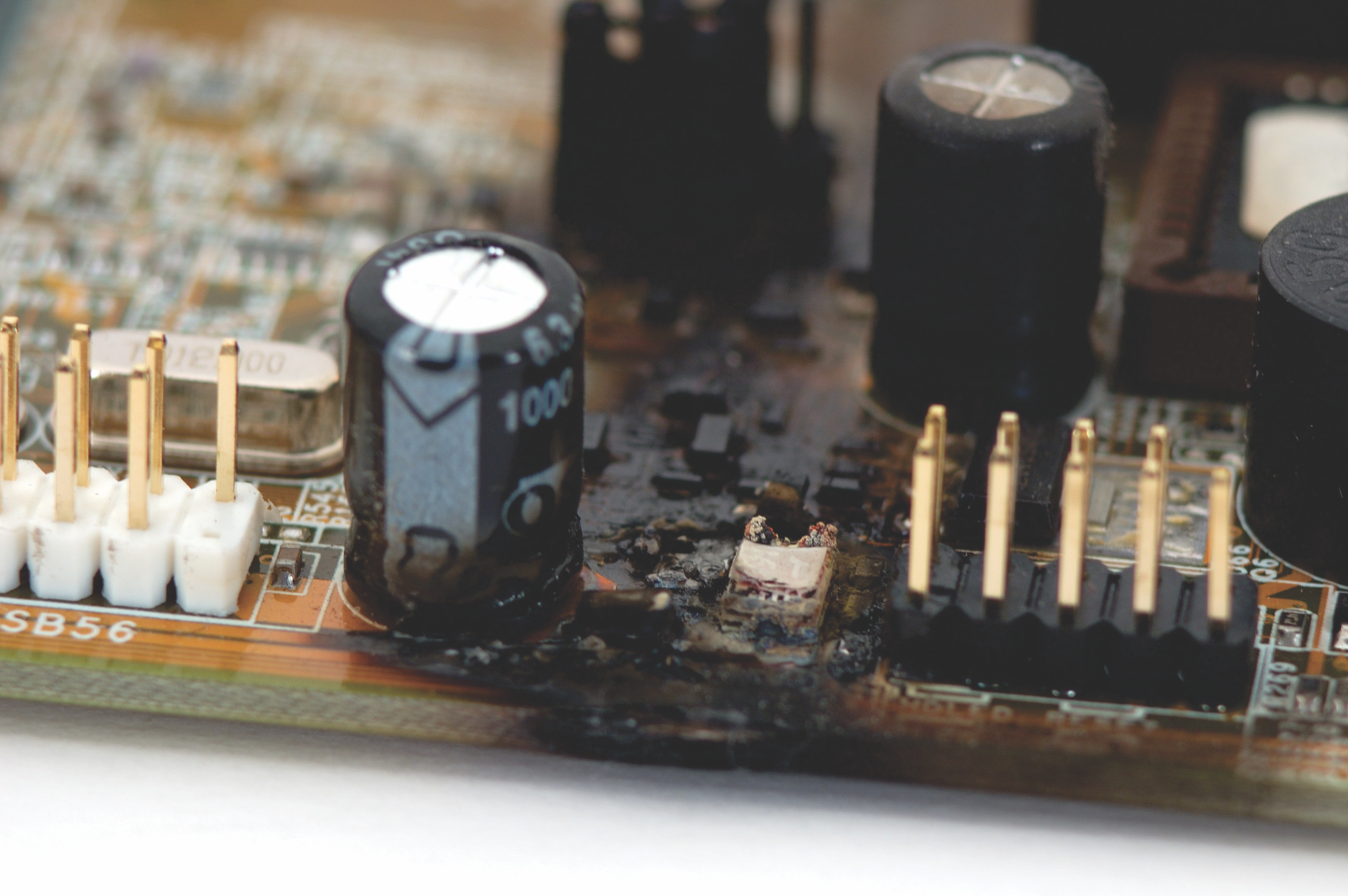
CircuitsFigure 1-2 shows catastrophic damage of the board due to protection circuits failure. Probability of the failure is high in a discrete components-based implementation. Selecting a proper integrated protection solution is critical to avoid possible system failure, unwanted downtime and bad reputation of the product.
 Figure 1-2 Impact of the Improperly
Designed Protection Circuits