SLVAE51A November 2018 – October 2020 LM7310 , TPS2100 , TPS2101 , TPS2102 , TPS2103 , TPS2104 , TPS2105 , TPS2110 , TPS2111 , TPS2111A , TPS2112 , TPS2112A , TPS2113 , TPS2113A , TPS2114 , TPS2114A , TPS2115 , TPS2115A , TPS2120 , TPS2121 , TPS25947
1 What is a Priority Power MUX?
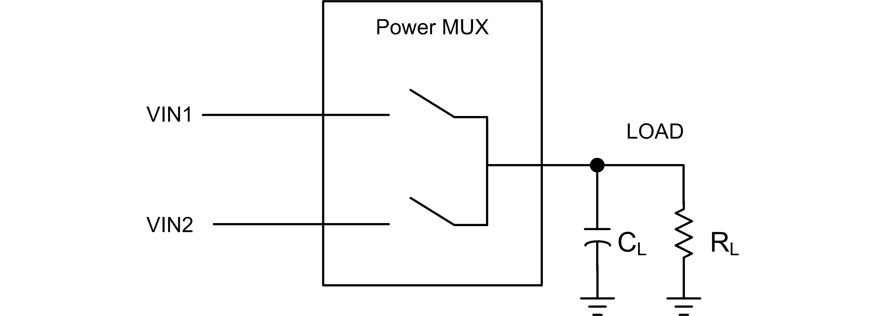
A basic Power Multiplexer (Power MUX) selects between two or more input supplies to power a single output.
 Figure 1-1 Power MUX Block
Diagram
Figure 1-1 Power MUX Block
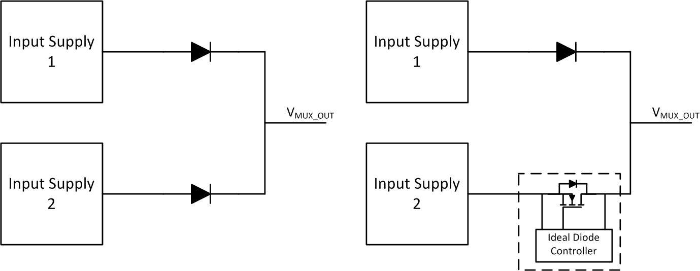
DiagramIf there is no preference for which input supply to use, or if the preference is to always use the highest input voltage supply available, then the minimum requirement for a power MUX solution would be reverse current blocking for each input path. This can be accomplished using any combination of diodes or ICs which behave like a diode (such as Ideal Diode Controllers).
 Figure 1-2 Minimum Functionality for
Power MUX Without Priority
Figure 1-2 Minimum Functionality for
Power MUX Without PriorityA schottky or silicon diode will result in a voltage drop around 0.4 V or 0.7 V, respectively. Using an ideal diode controller will result in a much lower voltage drop (on the order of 10 mV to 100 mV and there will be a parasitic body diode which must be positioned to block reverse current when the switch detects reverse current or is disabled.
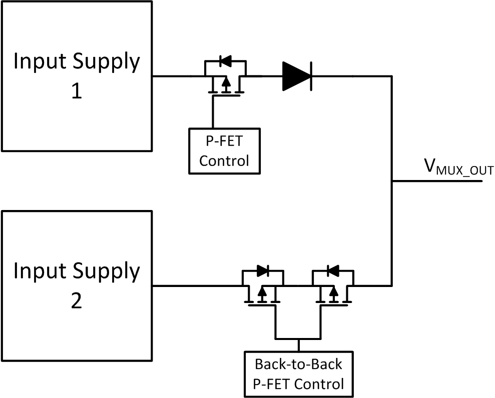
If there is a priority, then additional switches must be added to have full control over which path to enable. Reverse current blocking (through a diode or a FET) must remain present and now a MOSFET must be added to turn on/off each power path to the load.
 Figure 1-3 Example Priority Power
MUX
Figure 1-3 Example Priority Power
MUXThe focus of this application note will be on priority power MUX solutions and how they can be implemented.