SLVAE51A November 2018 – October 2020 LM7310 , TPS2100 , TPS2101 , TPS2102 , TPS2103 , TPS2104 , TPS2105 , TPS2110 , TPS2111 , TPS2111A , TPS2112 , TPS2112A , TPS2113 , TPS2113A , TPS2114 , TPS2114A , TPS2115 , TPS2115A , TPS2120 , TPS2121 , TPS25947
3.2 Semi-Integrated
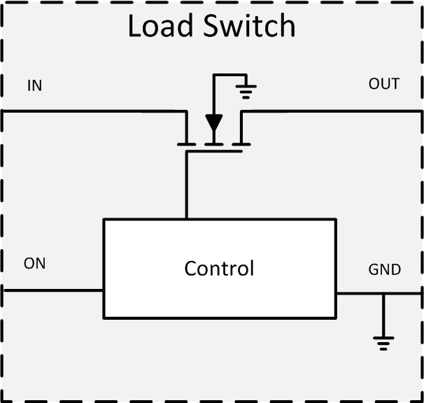
For low-voltage inputs (less than 5 V), there are load switches available with a single integrated MOSFET but have the ability to block reverse current when disabled. These switches can accomplish this by effectively removing the body diode of the integrated FET while the switch is disabled.
 Figure 3-2 Load Switch with Parasitic Body Diode Removed
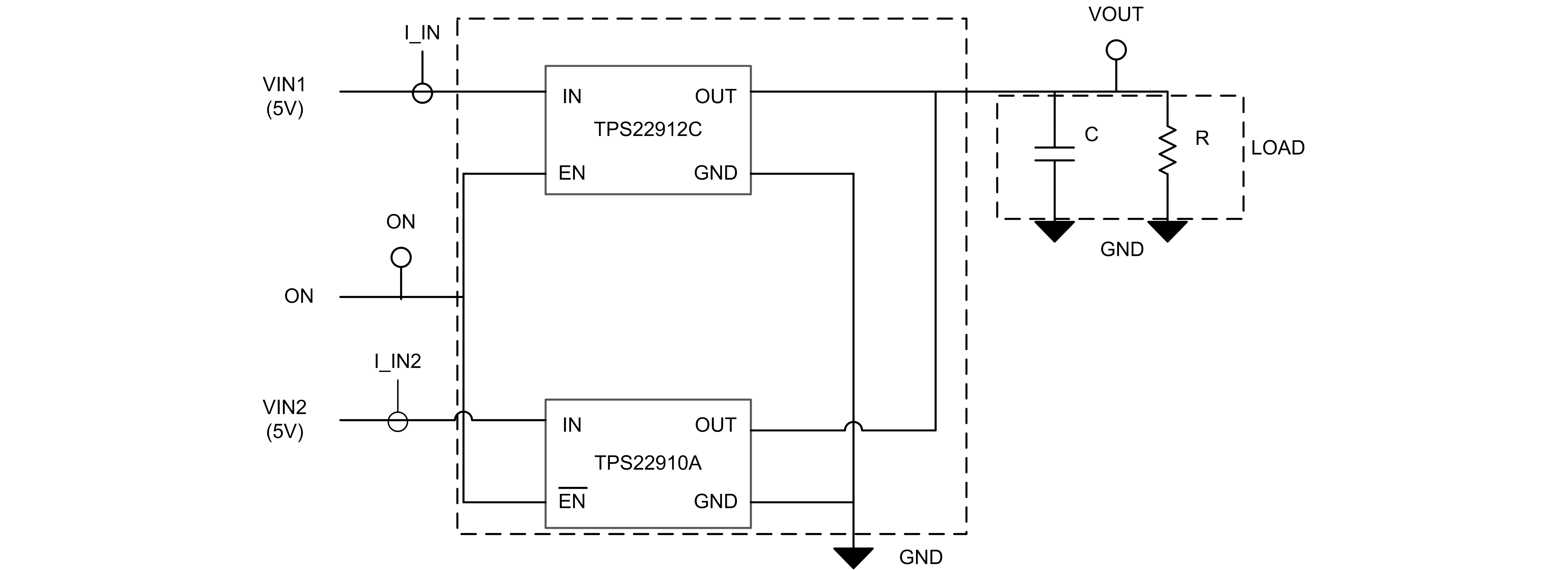
If using one of these load switches with an active high enable and another load switch with active low enable, you can select between each power path while using only 1x GPIO.
 Figure 3-3 Semi-Integrated Power MUX using TPS22910 and TPS22912 Load Switches
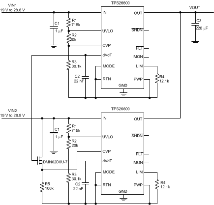
For higher input voltages (> 5 V), there are eFuse switches available with back-back MOSFETs. They can be used in a priority mux configuration (see Figure 3-4).
 Figure 3-4 Semi-Integrated Power MUX using 2x TPS2660 eFuses
To learn more about how to use load switches or eFuses in a MUX configuration, see Power Multiplexing Using Load Switches and eFuses.