SLVAE59A February 2019 – April 2022 DRV8242-Q1 , DRV8243-Q1 , DRV8244-Q1 , DRV8245-Q1 , DRV8343-Q1 , DRV8702-Q1 , DRV8702D-Q1 , DRV8703-Q1 , DRV8703D-Q1 , DRV8803 , DRV8804 , DRV8805 , DRV8806 , DRV8860 , DRV8873 , DRV8873-Q1 , DRV8874 , DRV8874-Q1 , DRV8876 , DRV8876-Q1 , DRV8935 , DRV8955
4.2 Independent Low-/High-Side Driving
For high-side and/or low-side driving, some devices have an independent FET mode that can drive separate high-side and low-side loads. Both the DRV8714-Q1 and DRV8343-Q1 gate drivers support several drive configurations.
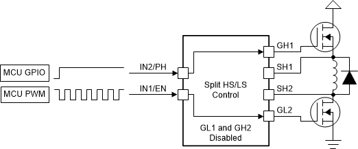
The DRV8714-Q1 has a split high-side and low-side control feature which enables connecting a floating load in between HS and LS FETs. The diagram below shows DRV8714-Q1 driving a solenoid load in this configuration.
 Figure 4-3 DRV8714-Q1 Split HS/LS
Control
Figure 4-3 DRV8714-Q1 Split HS/LS
ControlIn this mode, the HS FET can be controlled as a switch, and the LS FET can be controlled by PWM.
The highly configurable DRV8343-Q1 can support several configurations of phases, for example, where one phase of three could be a half-bridge and others are independent FETs, one is PH/EN and others are PWM, and so forth.
For the Independent MOSFET drive mode, the INHx and INLx pins control the outputs, GHx and GLx, respectively. This control mode. In this mode, turning on both the high-side and low-side MOSFETs at the same time in a given half-bridge gate driver is possible. In this mode, the integrated dead time is bypassed.
| INLx | INHx | GLx | GHx |
|---|---|---|---|
| 0 | 0 | L | L |
| 0 | 1 | L | H |
| 1 | 0 | H | L |
| 1 | 1 | H | H |
Figure 4-4 shows how the DRV8343-Q1 device can be used to connect a high-side load and a low-side load at the same time with one half-bridge and drive the loads independently. In this mode, the VDS monitors are active for both the MOSFETs to protect from an overcurrent condition. This can be done for each of the 3 phases for a total of 6 different solenoids. Note that if a half-bridge is used to only implement a high-side or low-side driver, the unused does not need to be connected. VDS monitors can still monitor for overcurrent condition.
 Figure 4-4 Independent PWM High-Side and
Low-Side Drivers