SLVAEP4 October 2023 BQ79600-Q1 , BQ79612-Q1 , BQ79614-Q1 , BQ79616 , BQ79616-Q1 , BQ79652-Q1 , BQ79654-Q1 , BQ79656-Q1
5.2 Capacitor Only Isolation
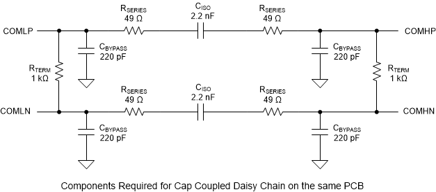
For low noise environments or devices mounted on the same pcb, typically the best practice is to choose capacitors only for isolation. We recommend these capacitors to be 2.2nF, high voltage rated (twice the voltage of the system's total pack voltage), and automotive qualified. Our reference schematic uses the 1206J2K00222KXR supplied by Knowles. Use of a capacitor of up to 5.6nF for this isolation is possible.
 Figure 5-2 Capacitors Only Across PCBs
 Figure 5-3 Capacitor Only on Same PCB