SLVUBE6C November   2018  – July 2021 TPS56339


  1.   Trademarks
  2. 1Introduction
  3. 2Performance Specification Summary
  4. 3Modifications
    1. 3.1 Output Voltage Set Point
    2. 3.2 Adjustable UVLO
  5. 4EVM Photos
  6. 5Test Setup and Results
    1. 5.1  Input/Output Connections
    2. 5.2  Start-Up Procedure
    3. 5.3  Efficiency
    4. 5.4  Output Voltage Load Regulation
    5. 5.5  Output Voltage Line Regulation
    6. 5.6  Load Transients
    7. 5.7  Voltage Ripple
    8. 5.8  Powering Up
    9. 5.9  Powering Down
    10. 5.10 Output Short Protection and Recovery
    11. 5.11 Thermal Performance
  7. 6Board Layout
    1. 6.1 Layout
  8. 7Schematic and List of Materials
    1. 7.1 Schematic
    2. 7.2 List of Materials
  9. 8Revision History

Voltage Ripple

Figure 5-7, Figure 5-8 and Figure 5-9 show the TPS56339EVM output voltage ripple for full-load, skip-mode, light-load and no-load operation. VIN = 19 V. The output The ripple voltage is measured directly across the output capacitors.
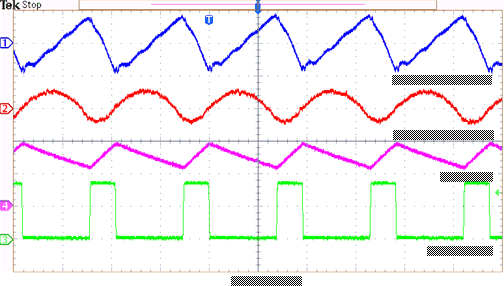
GUID-B2F531D5-E558-4728-84B7-A76C337C492E-low.gifFigure 5-7 TPS56339EVM Output Ripple, IOUT = 3 A
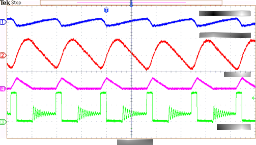
GUID-98662339-D151-4683-ACBD-B29967A38205-low.gifFigure 5-8 TPS56339EVM Output Ripple, IOUT = 0.3 A
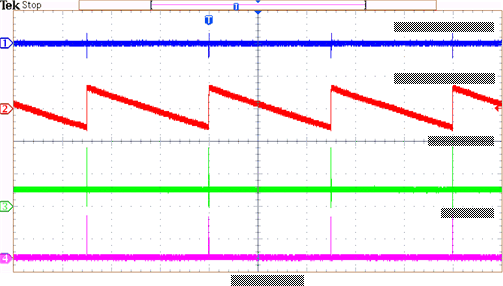
GUID-7E69AF1B-0068-4FD0-BEDA-DA4A6C48ED9F-low.gifFigure 5-9 TPS56339EVM Output Ripple, IOUT = 0 A