SLVUBW7 May 2020
- TPS7H4001QEVM-CVAL Evaluation Module User's Guide
4.8 Current Limiting
Finally, it is worth mentioning the behavior of the device with regards to current limiting. Although, the recommended operating condition (ROC) of the device is to never exceed 18-A peak current per converter, the design is robust enough to handle output currents up to the limiting mechanism of the device, which is typically 25 A, without damage to the DUT. This does not mean that external components cannot be damaged so it is imperative that the ratings of these components be in line with intended and, potential, unintended operational conditions.
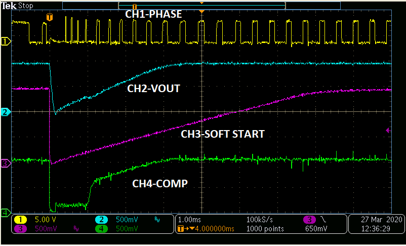
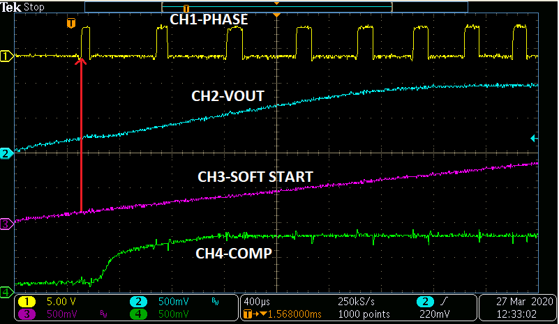
Figure 13 shows what happens when the high side current limit threshold is exceeded. The soft start pin is pulled low which causes the switching phase node to stop switching. This, in turn, causes the output voltage to drop causing VSENSE (not shown) to drop. Only after the soft start pin re-establishes a voltage level equal to the VSENSE pin (VOUT) does the device start switching again as shown in zoomed out version of Figure 14.
 Figure 13. High Side Current Limiting
  Figure 14. High Side Current Limiting - Zoomed In