SNAU287 November 2023
- 1
- Description
- Features
- 4
- 1Evaluation Module Overview
- 2Hardware
- 3Software
- 4Hardware Design Files
- 5Additional Information
- 6Related Documentation
3.1.3.1 Registers
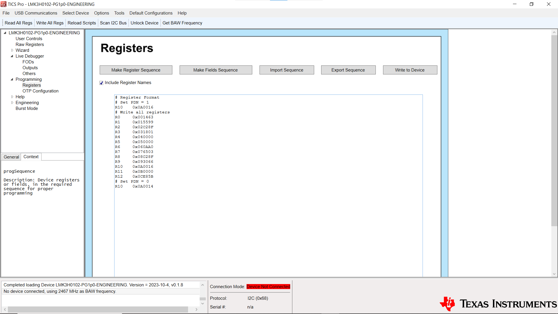
 Figure 3-13 LMK3H0102 Registers Page
The Registers page allows for bulk reading and writing of the device registers. The Make Register Sequence button generates a register sequence for writing all required registers to the device. This includes setting the PDN bit to a '1' before modifying registers, and setting the bit to a '0' afterward. The Include Register Names checkbox inserts the register name before the register data, separated by a tab. The registers can be written field-by-field using the Make Fields Sequence button. Sequences can be imported into and exported from the GUI using the Import Sequence and Export Sequence buttons. The contents of the progSequence field below the buttons can be written to the device using the Write to Device button.
Custom data can be written to the device using the progSequence and Write to Device buttons. The requirements for custom data are as follows:
- Empty lines are ignored.
- Comments must start with the '#' character.
- Registers can be data only, or register name and data. If register name and data, these must be separated by a tab or a single space.
- Field names and data can be specified. If so, these must be separated by a tab or a single space.