SNLA364C March 2021 – June 2022 DP83TD510E
- Abstract
- Trademarks
- 1 Introduction
- 2 1-V and 2.4-V p2p Mode Scripts
- 3 Time-Domain Reflectometry
- 4 Active Link Cable Diagnostics
- 5 Signal Quality Indicator
- 6 Cable Diagnostics Summary
- 7 Loopback Modes
- 8 Pseudo-Random Bit Sequence Functions
- 9 USB to MDIO Procedure
- 10IEEE 802.3cg PMA Compliance
- 11Revision History
7 Loopback Modes
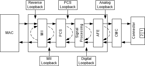
There are several loopback options within the DP83TD510E that test and verify various functional blocks within the PHY. Enabling loopback modes allow for in-circuit testing of the digital and analog data paths. The DP83TD510E may be configured to any one of the Near-End Loopback modes or to the Far-End (reverse) Loopback mode. MII Loopback is configured using the Control Register (BMCR, address 0x0000). All other loopback modes are enabled using the BIST Control Register (BISCR, address 0x0016).
 Figure 7-1 Loopback Test Modes