SNOA957B September 2016 – June 2021 LDC0851 , LDC1001 , LDC1001-Q1 , LDC1041 , LDC1051 , LDC1101 , LDC1312 , LDC1312-Q1 , LDC1314 , LDC1314-Q1 , LDC1612 , LDC1612-Q1 , LDC1614 , LDC1614-Q1 , LDC2112 , LDC2114 , LDC3114 , LDC3114-Q1
4.1 Perfect Target Material Characteristics
From an electrical perspective, the perfect target material needs to have the highest possible conductivity for optimum inductive measurements. The highest possible conductivity results in the most generated eddy currents; the eddy currents create the strongest opposition magnetic field. The stronger magnetic field results in a larger shift in the sensor inductance, which can be measured with more resolution.
Silver, the highest conductivity metal, is the optimum target material based on this parameter. However, other characteristics such as cost limit the suitability of silver.
From a mechanical perspective, the target material should be physically stable and exhibit uniform movement without warping or tilting, which could be incorrectly measured as a position shift. The material's thermal expansion coefficient should be as low as possible so that any temperature change does not change the effective position of the target.
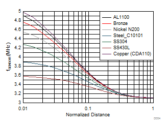
Figure 4-1 shows the change in sensor frequency vs target position for targets of different materials. A larger frequency shift is desirable; since the LDC can measure the larger shift can with more resolution. Unfortunately, a silver target was not available for comparison.
 Figure 4-1 Comparison of Sensor Frequency Shift for Different Target Metals
The data used in Figure 4-1 was collected for a 14 mm diameter circular sensor with a free space resonant frequency of 3.11 MHz. The target distance is scaled by the sensor diameter, so the 0.1 value on the X-axis corresponds to a sensor to target distance of 1.4 mm.