SNOAAA5 April 2024 DRV8220 , FDC1004-Q1 , LDC3114-Q1 , TMAG5131-Q1 , TMAG5173-Q1 , TMAG6180-Q1
- 1
- Abstract
- Trademarks
- 1Introduction
- 2Automotive Door Handle Architectures
- 3Functional Demo Design
- 4Detailed Design Flow for Door Handle Functions
- 5Summary
- 6References
4.2.1 Demo Implementation of Deployable Door Handle Position Sensing Using TMAG6180-Q1
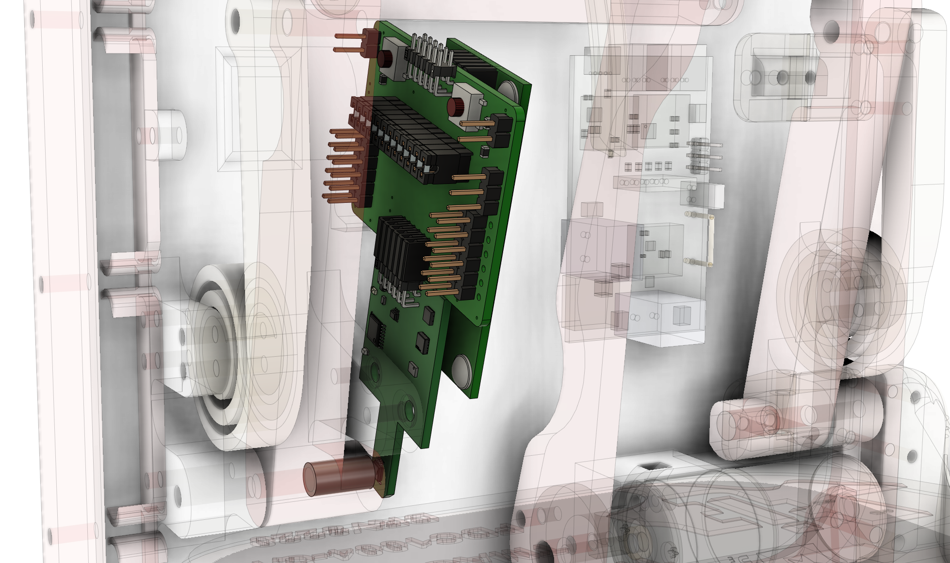
In this demo, a TMAG6180-Q1 automotive high-precision analog AMR angle sensor with 360 degree angle range is used to monitor handle position. A diametric magnet is embedded in the handle assembly and centered on the handle's axis of rotation, as shown in Figure 4-11. The TMAG6180-Q1 is mounted so that the AMR sensing element is centered in an on-axis alignment, with the top of the TMAG6180-Q1 about 1.5mm away from the surface of the magnet. The magnet has a height of 12mm and a radius of 3.18mm. The handle is roughly 98.52mm away from the axis of rotation, meaning that for each degree of rotation, the handle moves about 1.72mm.
 Figure 4-11 TMAG6180-Q1 Placement and Magnet Embedded in Handle
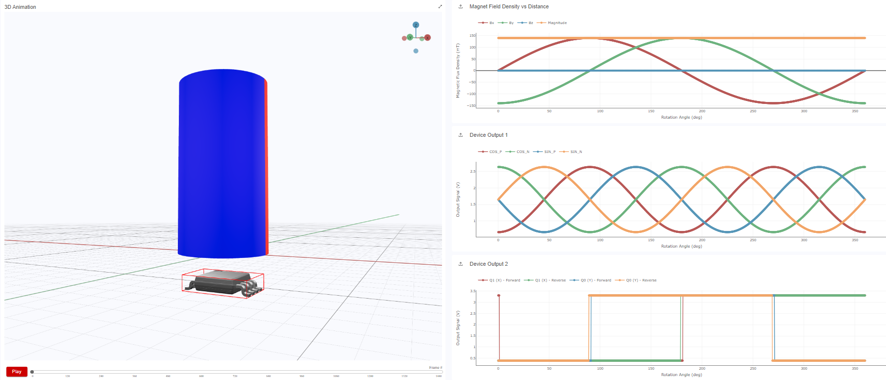
Figure 4-12 shows the simulation results from TI Magnetic Sense Simulator (TIMSS) for these magnet and sensor locations over a 360 degree rotation. The first plot shows the changing X and Y vectors of the magnetic field as the magnet rotates. With the amplitudes well-matched due to the on-axis alignment. The second plot shows the changing differential sine and cosine analog outputs from the TMAG6180-Q1. Notice that for every 360 degree rotation of the external magnetic field, the AMR outputs provide two periods. This is because the outputs have an electrical range of 180. If the mechanical angle between the sensor reference and the direction of the magnetic field is , then the AMR outputs correspond to and respectively. By utilizing the digital outputs of the Hall sensors shown in the third plot, the angle range of the AMR sensor can be extended to 360 degrees. Mechanical tolerances can also be simulated in TIMSS using the parametric sweep feature to see the potential impact on angle measurements.
 Figure 4-12 TMAG6180-Q1 TIMSS Simulation Results
In the GUI for this demo, the sine and cosine outputs of the TMAG6180-Q1 and the Q0 and Q1 outputs are used in an arctan2 calculation to determine the handle's angle of rotation.
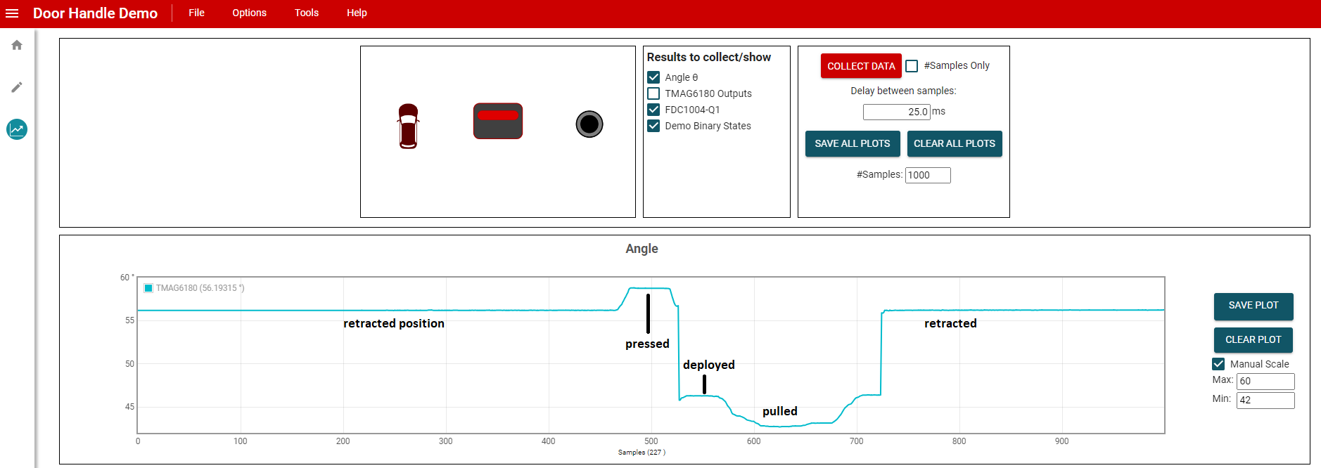
The angle plot in Figure 4-13 shows the handle angle measured by the TMAG6180-Q1 over time. In the demo, the handle angle measures approximately 56° when the handle is resting in the door, and approximately 46° when fully driven out by the DRV8220. The handle is driven out 17.4mm away from the door, which supports the previous calculation that the handle is extended roughly 1.72mm for each degree of rotation.
These angle limits can be adjusted if the user desires the handle to be deployed more or less. Additionally, the handle measures approximately 59° when pressed in by the user and approximately 45° or less then pulled by the user. These angle measurements make it easy to implement other functions that are initiated when the handle is pressed, or to ensure the handle does not retract while a user is pulling on the handle. The full operation of depoyable door handle position detection in the demo is shown in this video.
 Figure 4-13 Door Handle Angle of Rotation Plot