SPRUJ32 October 2022
5 Frequently Asked Questions (FAQs)
- Can other programming and debug tools (such as an XDS200 debug probe) be used
with the F280013x LaunchPad?
- The F280013x LaunchPad utilizes an on-board XDS110 debug probe in a 2-pin cJTAG configuration. cJTAG only uses the TMS and TCK pins of the debug probe. TDI and TDO are present on tJ101 and can be connected to a debug probe through jumper wires, if necessary.
- What versions of Code Composer
Studio IDE can be used to develop software for the F280013x LaunchPad?
- The on-board XDS110 debug probe is compatible with Code Composer Studio IDE version 6.1.0 and later.
- Why can't I connect to the
LaunchPad in Code Composer Studio IDE?
- Are shunts present on J101 for TCK and TMS?
- Is the XDS110 and the F2800137 MCU powered? Are LED0
and LED1 illuminated? See Section 3.1.2 for further details on powering the LaunchPad.
- If JP1 shunts are disconnected, the power provided through the USB is isolated from the rest of the board. Make sure that 3.3 V is supplied to any of the available connectors on the target side of the isolation.
- Is the USB-C cable connected to the PCB and is the USB
region receiving power? Is LED7 illuminated?
- The USB region must be powered with the 5 V from the USB cable. LED7 illuminates when 5-V USB power is connected. The USB isolation chip requires 5 V on the USB side to operate and pass the signals across the isolation barrier.
- Make sure that the target configuration is set up to
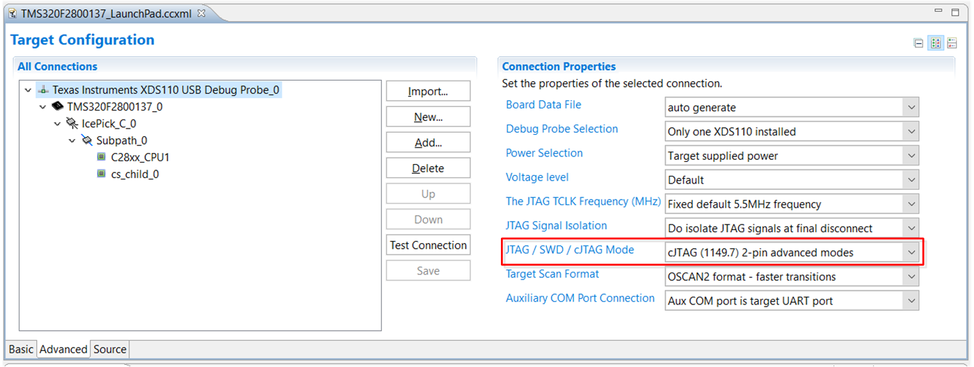
use cJTAG in 2-pin advanced mode. Open the Target Configuration file
(.ccxml) in the Code Composer Studio IDE. Click on the Advanced tab and
select cJTAG (1149.7) 2-pin advanced modes from the drop-down labeled
JTAG/SWD/cJTAG Mode. Leave the Target Scan Format as OSCAN2 format.
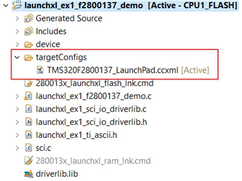
Alternately, a working Target configuration file is included in the
launcxl_ex1_F2800137_demo project "TMS320F2800137_LaunchPad.ccxml". You
can use this without modifications.
 Figure 5-1 Target
Configuration Advanced Options
 Figure 5-2 Target
Configuration Included in the Demo Project
- Why is the serial connection not working?
- Are shunts present on J101 for TXD and RXD?
- Are you using the correct COM port?
- Right click on My Computer and select Properties. Navigate to the Hardware tab in the dialog box and open the device manager. Scroll to Ports (COM and LPT) and expand this entry. Is XDS110 Class Application/User UART listed? If so, read the COM number to the right of the entry; this is the COM number you use.
- Are you using the correct baud rate? Most, if not all, of the examples are configured for a baud rate of 115200 when the CPU is running at 100 MHz. If you have changed the PLL settings or developed your own code, you have to recalculate the baud rate for your specific application. For information on how to do this, see the TMS320F280013x C2000 Real-Time Microcontrollers Technical Reference Manual.
- Does the UART channel wired to the debug probe match
the UART channel configured in software?
- The F280013x LaunchPad provides an option for one of two possible UART channels to be routed to the debug probe through J101. Make sure that S2 is configured to the appropriate UART channel for the application software. See Section 3.3.2 for details.