SSZTAO9 november 2016 TMS320F28069M
Resolvers provide accurate and high-reliable position feedback in industrial drives like servo drives, especially in harsh industrial environments with dust and temperatures above 150°C. A resolver is an absolute mechanical angle sensor and operates as a variable coupling transformer. This means that the amount of magnetic coupling between the primary winding and two secondary windings varies according to the angle position of the rotating element (rotor), which is typically mounted on the motor shaft. Resolvers can withstand severe conditions for a very long time, making them the perfect choice for industrial motor controls, servos, robotics (including service robots and manufacturing robots), power-train units in hybrid- and full-electric vehicles, and many other applications that require precise shaft rotation.
Industrial drive manufacturers using resolvers in their designs tend to care about robustness, the reliability of the absolute angle measurement and the overall system cost. Because a resolver involves differential signals for input as well as output, this greatly improves their ability to reject common-mode noise. Electromagnetic compatibility (EMC) plays a major role in defining drive robustness. EMC compliance to specific standards is a must. Most industrial servo drives typically use shielded cables to connect to the motor and position-feedback sensor like the resolver. Cable lengths can be 100m and even more. At longer cable lengths, impulse noise currents on the cable’s shield induced by the inverter’s pulse-width modulation (PWM) switching can couple into the resolver’s differential signal pairs. Very fast transient bursts – like crosstalk from the switching inverter power cable with high dV/dt in the range of ~10kV/µs – can impact the performance of resolver-to-digital converters (RDCs).
The recently released EMC-Compliant Single-Chip Resolver-to-Digital Converter (RDC) Reference Design provides a solution for EMC-compliant RDC through a single-chip PGA411-Q1 with 12-bit angle resolution. See Figure 1.
 Figure 1 Simplified System Block
Diagram of the TIDA-00363 Reference Design with F28069M MCU LaunchPad™
Development Kit
Figure 1 Simplified System Block
Diagram of the TIDA-00363 Reference Design with F28069M MCU LaunchPad™
Development KitWhat Benefits Does This Design Provide?
- Overall reduction in Bill of Material (BOM) and Printed Circuit Board (PCB) size. Traditionally, RDCs have required an additional exciter amplifier, along with a power supply for the exciter amplifier, to drive the sine and cosine excitation signals. The additional semiconductor components tend to take up more space, and require additional extra passive components in the BOM. The RDC reference design uses the highly integrated PGA411-Q1 RDC, which integrates an excitation amplifier and boost circuit to power the excitation amplifier. With a 150mA output current and a programmable (10V-17V) boost power supply, the PGA411-Q1 enables a 60% reduction in PCB size compared to competing solutions. The programmability and flexibility of the PGA411-Q1 enables designers to use a wide range of resolvers. The PGA411-Q1 leverages analog multiply and subtract, along with a Type-II PI digital tracking loop, to perform angle and velocity calculations without the need for an analog-to-digital converter. For various evaluation methods, the design supports the SPI interface (8MHz, 3.3V I/O), parallel (12-bit) interface and ABZ/UVW encoder emulation output interface.
- Easy real-time evaluation of the TI reference design. Use the example firmware on the TMS320F28069M Microcontroller, to evaluate the reference design’s performance with the TMS320F28069M InstaSPIN-MOTION™ LaunchPad development kit. Angle data is available at a 16kHz sample rate for angle readout and register configuration through the USB virtual COM port.
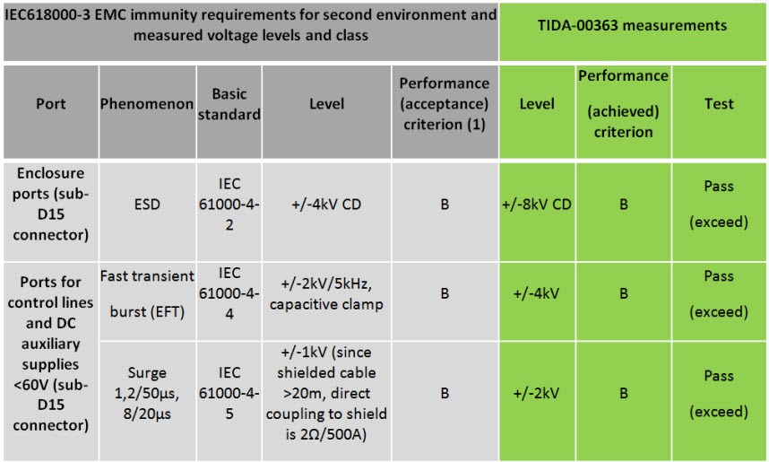
- EMC compliance. The
reference design is fully tested for IEC 61000-4-2, 4-4 and 4-5 (ESD, EFT, and
surge) with test levels and performance criterion specified in the IEC 61800-3
standard, “Adjustable speed and electrical power drive systems – Part 3: EMC
requirements and specific test methods.” The design is compliant to these
standards and exceeds the voltage requirements according to IEC 61800-3 EMC
immunity requirements by a factor of two. See Table 1.Table 1 TIDA-00363 EMC Immunity Test Results According to IEC618000-3
- Ability to measure the angle
step response. Many drive applications have dynamic change in the angle;
the RDC should be able to respond to these changes. The RDC reference design is
tested for two small-angle step responses: 1 degree and 5 degrees. Figure 2 shows the step response for a 1-degree change. The angle
settles to the required angle within 938µs.
 Figure 2 Step Response for
1-Degree Angle Change
Figure 2 Step Response for
1-Degree Angle Change - Measured angular accuracy.
The angular accuracy test uses two exciter voltage modes, at 7Vrms and 4Vrms.
Figure 3 shows the accuracy graph. Regardless of the mode and
voltages used for excitation, the angle accuracy is better than ±2.5 Least
Significant Bit (LSB).
 Figure 3 Angle Error with 7Vrms
and 4Vrms Excitation Modes
Figure 3 Angle Error with 7Vrms
and 4Vrms Excitation Modes - Integrated flexible
diagnostics. Fault detection and diagnostics play a vital role in
defining motor-drive safety. The PGA411-Q1 has integrated features for fault
detection and provides extensive diagnostic coverage compared to existing
discrete solutions on the market. Apart from that, existing solutions today use
a fixed threshold for the diagnostics. These fixed thresholds typically vary or
shift from system to system. The PGA411-Q1 enables you to fine-tune sensor input
and output line faults within 4 bits of resolution. The most important faults
are related to disconnection of the resolver (open, short or miswiring to ground
for the resolver’s excitation signals or the sine or cosine signals). These
appear as errors over the serial interface of the RDC to the host processor. In
Figure 4, these potential faults are highlighted in red. We at TI
fully tested the reference design according to these faults, and the PGA411-Q1
successfully identified and reported each fault through the serial
interface.
 Figure 4 Important Faults
Related to the Resolver and RDC
Figure 4 Important Faults
Related to the Resolver and RDC
Solving many of the challenges for RDC application, this reference design provides highly integrated EMC-compliant solution with easy real-time evaluation.
Additional Resources
- Check out the companion TI reference design for automotive subsystems, Automotive Resolver-to-Converter Reference Design for Safety Application.
- Read the blog post, “Accuracy? Resolution? Arc minutes? How to take charge of your motor control design.”