SWRA759 November 2022
5.3 Start Testing
Power on the TIDA-010224 board. The serial tool receives a message as shown in Figure 5-1.
 Figure 5-1 Board UART Output Start
Page
Figure 5-1 Board UART Output Start
Page- Provisioning mode.
If there is no Wi-Fi AP connected, selecting ‘1’ makes the board enter into Hibernate (provisioning) mode for configuring AP SSID and Password into the demo board. Details are:
- Input ‘1’ makes the board enter hibernate.
- Select the video and
which audio to use. It is preparing to play the video after wake-up from
hibernate by the UART input. After the input is finished, the board
enters into hibernate.
 Figure 5-2 Select Video
Stream Type via UART
 - Input ‘1’ again, wake up board for provisioning, as shown in Figure 5-3.
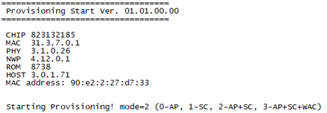 Figure 5-3 Provisioning
Status Output via UART
 - Open “SimpleLink Wi-Fi
Starter Pro” APP in cell phone.
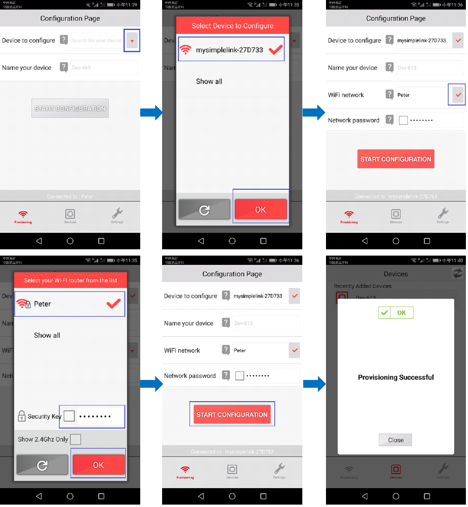 Figure 5-4 “SimpleLink
Wi-Fi Starter Pro” Configuration Processing
 - Click the ‘blue marked’ button.
- Select ‘mysimplexxx’.
- Select your Wi-Fi AP.
- Input password.
- Click the ‘start
configuration’ button and select ‘close’ to finish provisioning. UART
print as shown in Figure 5-5.
 Figure 5-5 Provisioning
IP Address Acquired
 - After provisioning, power off/on to restart demo board again. All of test functions could be continued.
- Hibernate mode.
This mode is for testing board current in hibernate, entering provisioning if there is no recognized Wi-Fi AP and watch video stream via APP. Details are:
After power on, input ‘1’ makes the board enter into hibernate mode. You can measure the current via 5 V power input connector. Typically, the current is about 20 µA.
When entering hibernate mode, any UART input wakes up the board and exits hibernate. Actually, UART input is similar with GPIO trigger input. This mode is quite similar with some applications that only need buttons or alarm inputs such as PIR input to wake up the system.
After waking up the board, it is ready to accept RTSP request. In this mode, you can run network stream APP to watch. As shown in Figure 5-6, click ‘+’ to add a new address, input rtsp address and port. For example, rtsp://192.168.0.103:554, choose UDP. Click ‘OK’(确定) to open video stream.
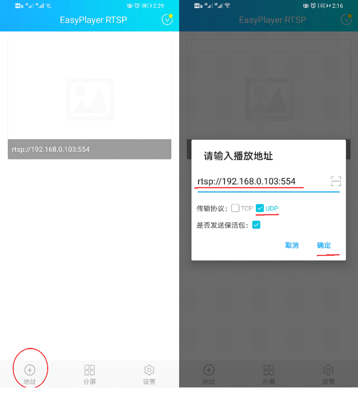 Figure 5-6 RTSP
ConfigurationNote: If measure current is in hibernate mode, make sure to disconnect with the JTAG cable and unplug the J1 jumper.
 - Intermittently Connected mode.
This mode is for the testing the board average current, which is intermittently sending status data to server and enters into hibernate. It is also woken up by any input via UART and entering into ready to accept RTSP request when it is in hibernate mode. Same as above, UART input is similar with the GPIO trigger input. This mode it is quite similar with some applications that report status and heartbeat signal to remote servers with long interval time. Details are:
- After power on, input ‘2’ makes the board enter into intermittently connected mode.
- Select video and which audio to use. It is preparing to play the video after wake-up from hibernate by the UART input.
- Input remote TCP server IP address such as 192.168.10.105.
- Input interval time in second such as 10.
- Board is woken up intermittently by RTC and sends 100 data to remote TCP sever again and again.
- Any UART input wakes up the board from hibernate to prepare accepting RTSP request mode.
- UART tool Print:
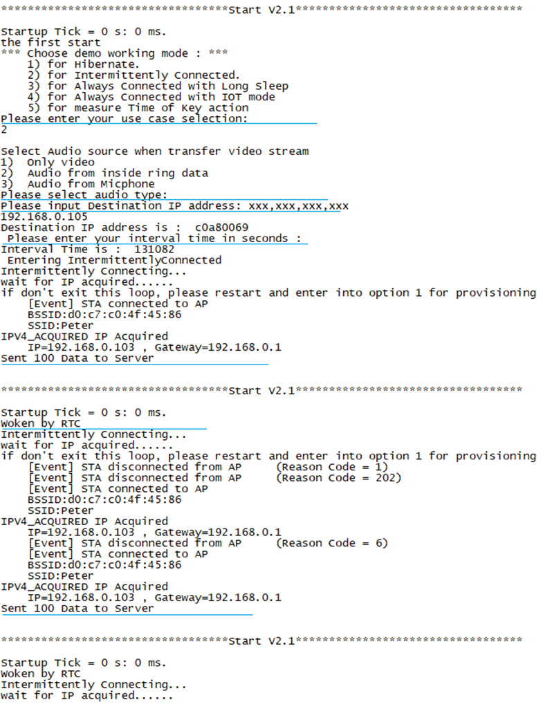 Figure 5-7 UART Printing
in Intermittently Mode
 - Net assist tool Print:
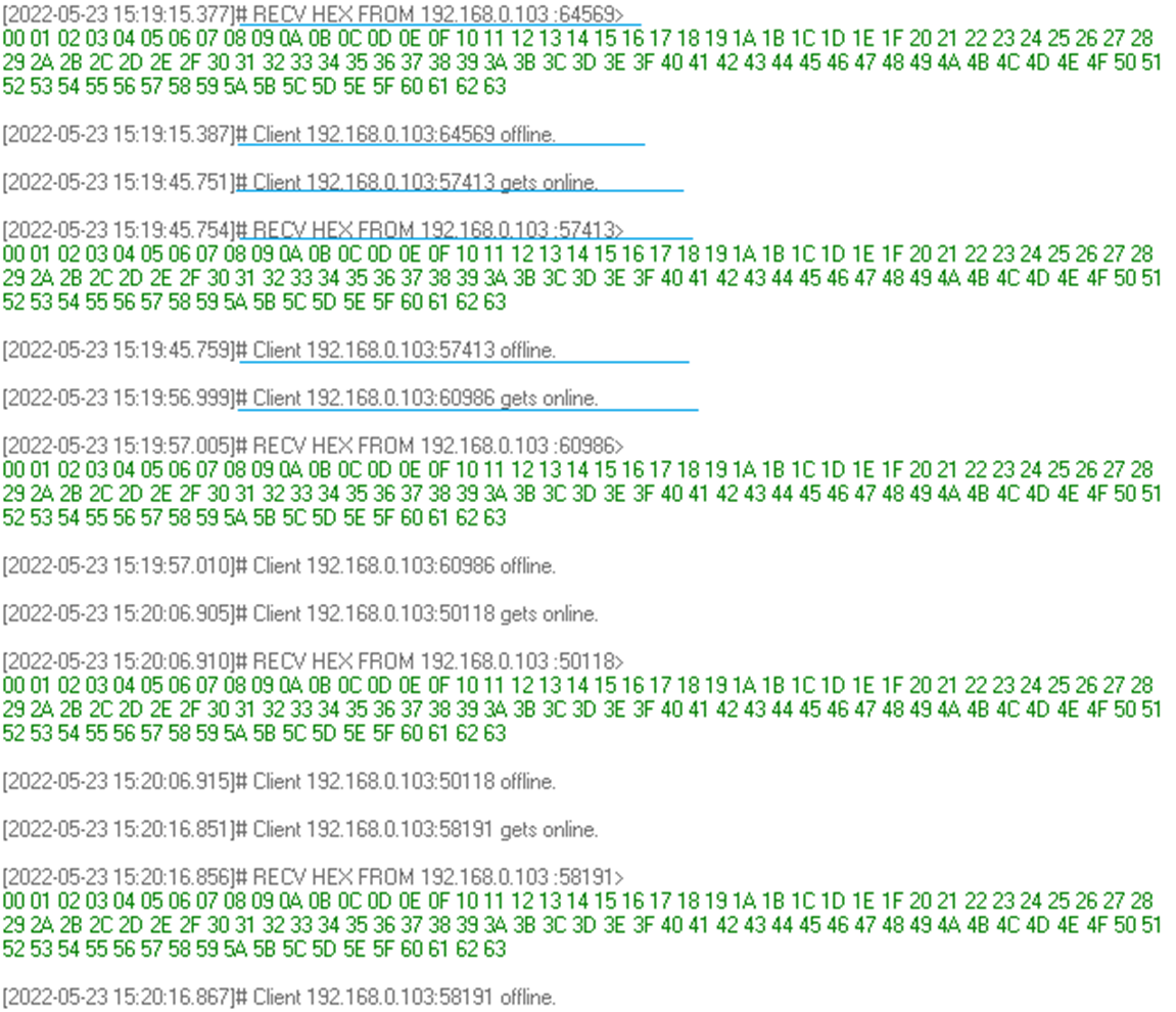 Figure 5-8 Net Assist
Receiver Printing in Intermittently Mode
Figure 5-8 Net Assist
Receiver Printing in Intermittently ModeIn Net printing, a new connection is created every time. The connection is lost between sending data.
Note: TCP server must be opened before finished configuration. If don’t receive TCP data in server, please try to close VPN or add net assist software in white list of firewall software.
- Always Connected with Long
Sleep/with IOT mode.
This mode is for testing board average current that is intermittently sending status data to the server and entering into LPDS. In this mode, the network connection between the test board and the Wi-Fi AP is not lost. It is also woken up by any input via UART when it is in LPDS. This mode it is quite similar with some application that only report status and heartbeat signals to remote servers, and are able to respond to server requests quickly because the connection socket is not lost in the remote server.
Note: IOT and Long Sleep mode need AP supporting.- Details are:
- After power on, input ‘3’ or ‘4’ will make board enter into Always Connected with Long Sleep or with IOT mode.
- Input beacon interval time to keep alive in AP connecting list.
- Select video and which audio from, it is preparing for play video after wake-up from hibernate by UART input.
- Input remote server IP address, such as 192.168.10.105.
- Input interval time of sending data in second, such as 10.
- Board will be woken up intermittently by RTC and send 100 data to remote TCP sever again and again.
- Any UART input will wakeup board from hibernate to prepare accepting RTSP request mode.
- UART tool print:
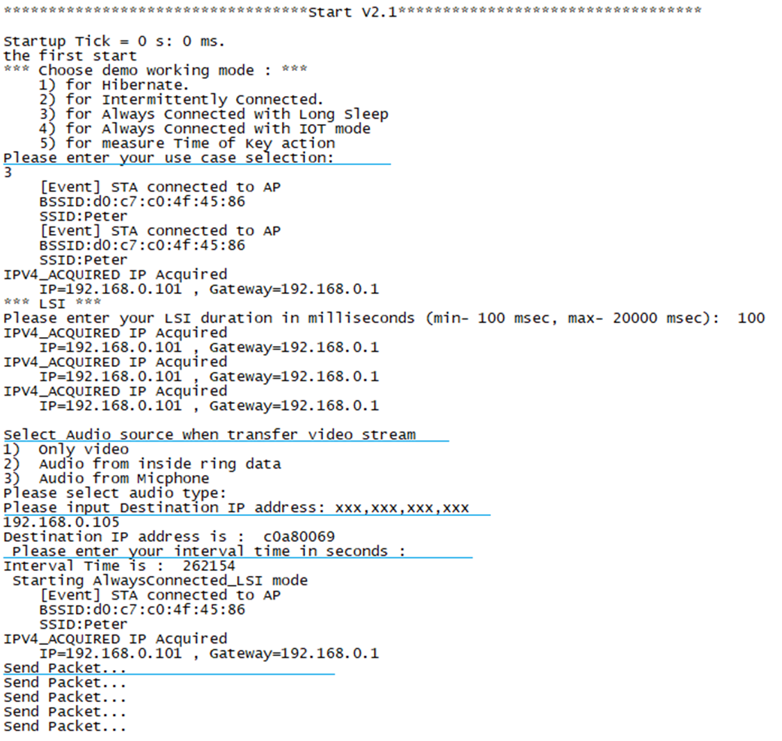 Figure 5-9 UART Printing
in Always Connecting Mode
 - Net assist tool print:
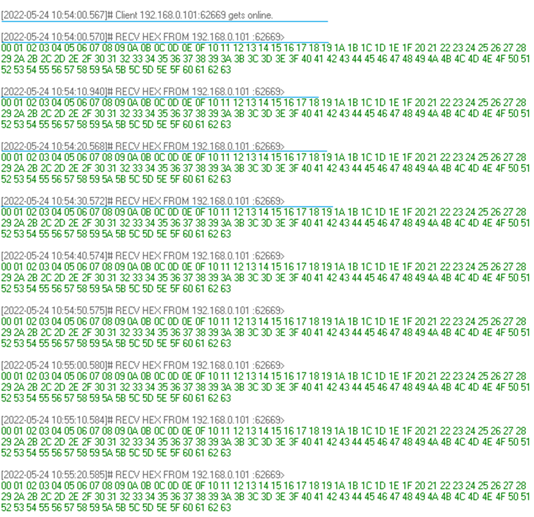 Figure 5-10 Net Assist
Receiver Printing in Always Connecting Mode
Figure 5-10 Net Assist
Receiver Printing in Always Connecting ModeIn Net printing, A new connection is created firstly, and it isn’t lost between sending data.
Note: TCP server must be open before finished configuration. If you do not receive TCP data in your server, try to close VPN or add net assist software in white list of firewall software.
- Details are:
- Measure Time of Key action.
This mode is for testing the board startup time that is from exiting hibernate to sending out the 10 frames of image. It is able to be woken up by any input via UART for testing. You can get the printing timestamp log via UART or test the wave via J13.2 pin with oscilloscope. Details are:
- After power on, input ‘5’ makes the board enter into Measure Time of Key action mode.
- Input remote server IP address such as 192.168.10.105. Then test board enters into Hibernate.
- Any input via UART wakes up board and send data out to remote TCP server after getting the image frame.
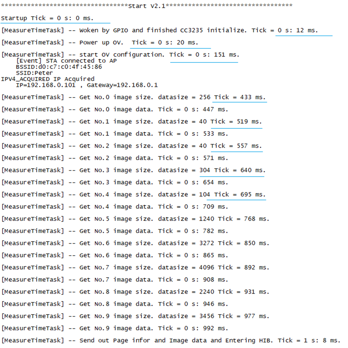 Figure 5-11 UART Printing in
Measure Startup Mode
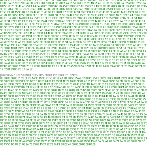 Figure 5-12 Net Assist Receiver
Printing in Measure Startup ModeNote: The startup time is affected by WIFI connection time, especially in the first time running.