SWRA759 November 2022
4.3 Upgrade OA7000 Firmware
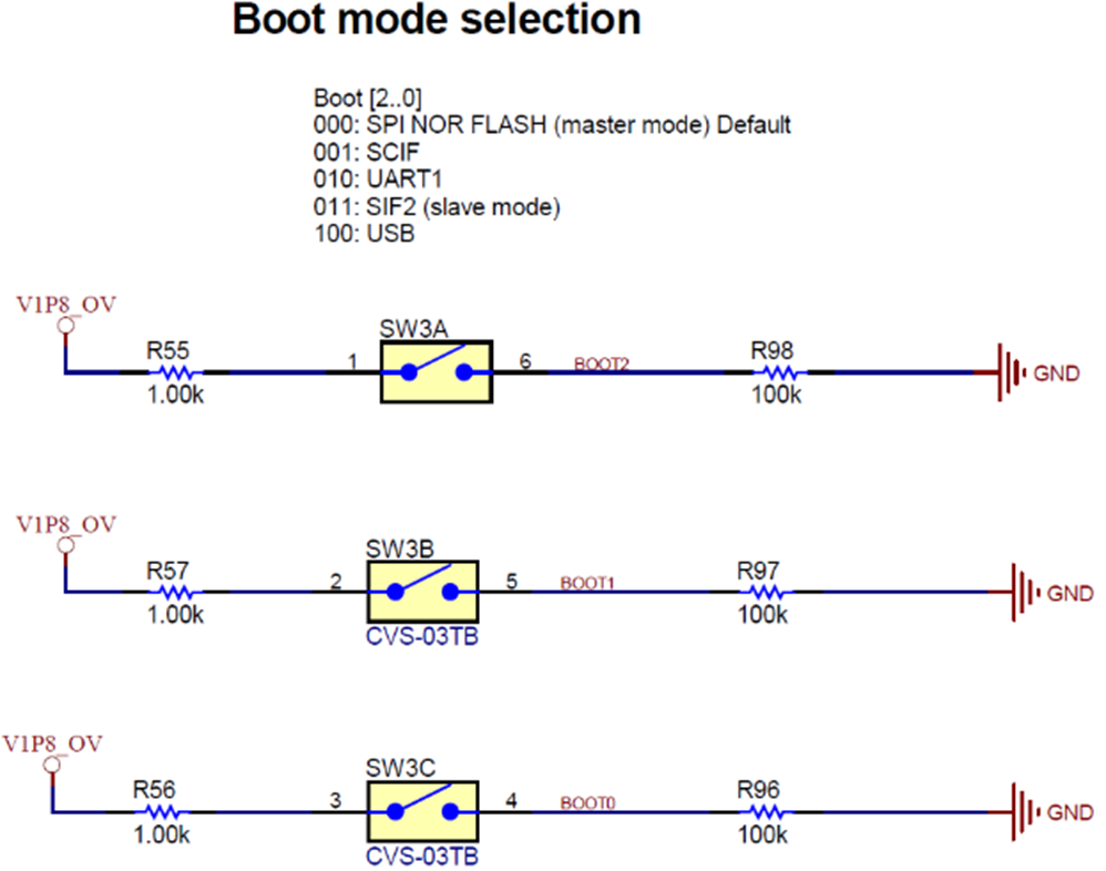
- Make SW3 jumper to ‘100’.
 Figure 4-9 SW3 Boot-Mode
Selection
 - Connect the microUSB cable to the PC and camera board.
- Connect the USB2Uart tool to the PC and camera board serial port as described in Section 4.2.
- Open the serial assist tool in the PC, and open the COMx port with ‘115200, 8 bit, None parity, 1 Stop bit, None handshaking’.
- Power up camera board via ‘USB power input’.
- Input ‘1’ for hibernate.
- Input ‘1’ for only video.
- Input any to wakeup camera board
from hibernate and power on OA7000.Note: Because OA7000 power is controlled by CC3235, first, you need power on OA7000.
- Open
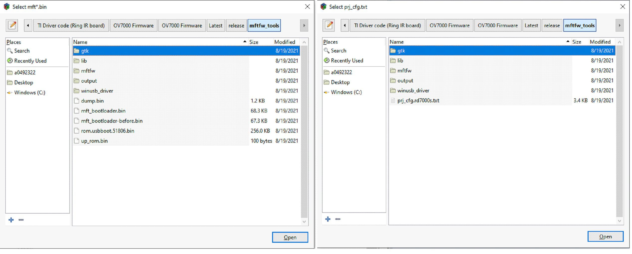
MFT.exe in mftfw_tools, select as shown in Figure 4-10.
 Figure 4-10 MFT Tool Setting Page
1
 - Double click ‘mftfw’->oa7000s->mftfw.bin in ‘Select mft*.bin’ dialog. Then a new dialog window pops up named ‘Select prj_cfg.txt’.
- Double click
‘prj_cfg.rd7000s.txt’. It returns the main dialog named ‘OA7000 MFTxxxxx’.
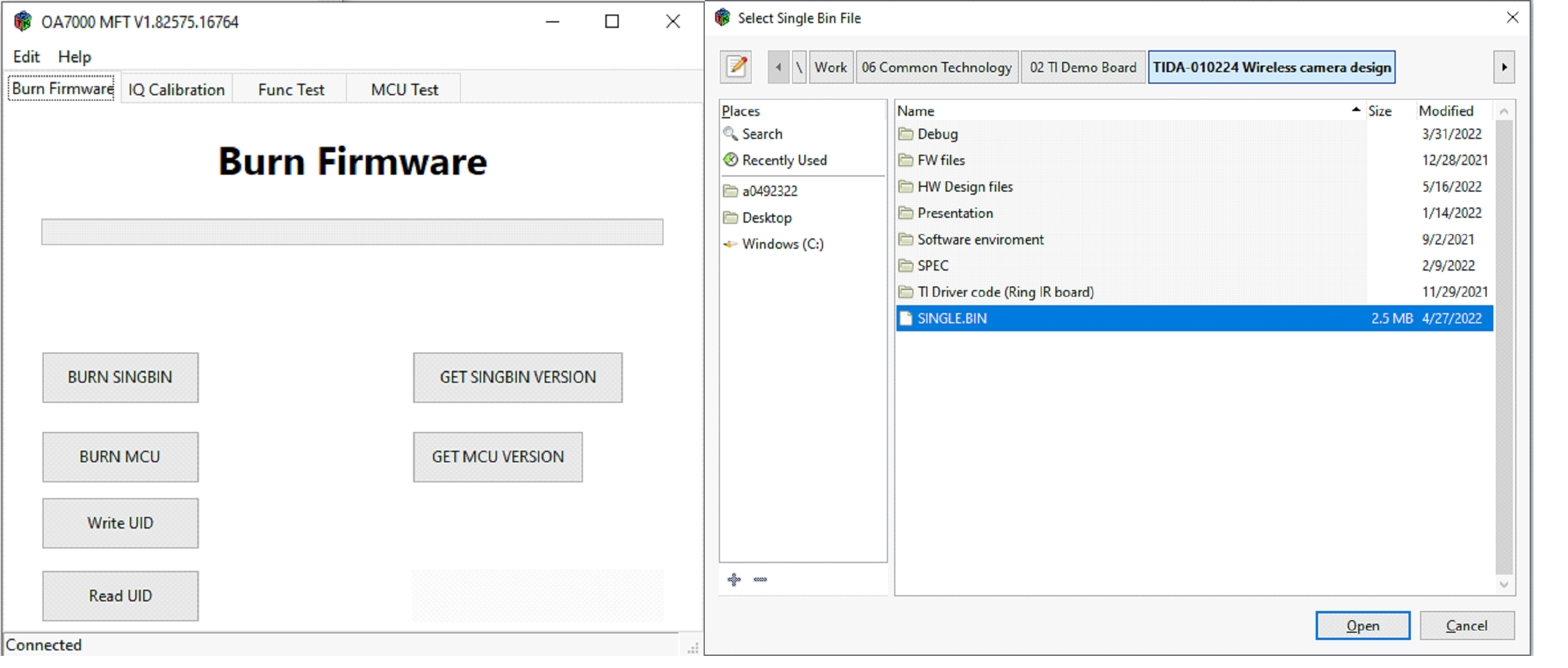
 Figure 4-11 MFT Tool Setting Page
2
 - In this dialog, it shows ‘Connected’. Click the ‘BURN SINGBIN’ button.
- Find ‘SINGLE.BIN’ and double
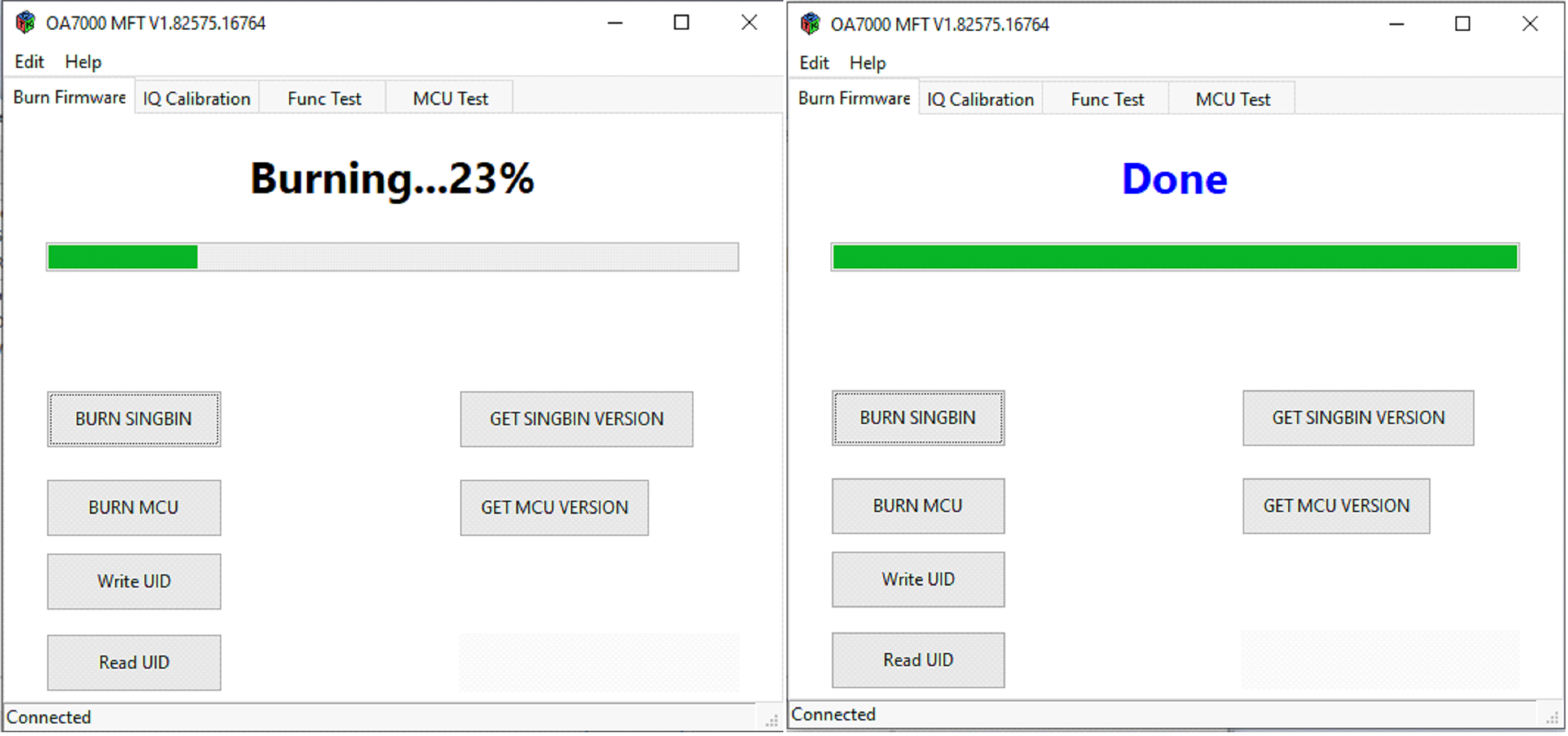
click it. bin file burns to OA7000.
 Figure 4-12 MFT Tool Setting Page
3